X9SPV-F X9SPV-LN4F USER’S MANUAL Revision 1.
The information in this User’s Manual has been carefully reviewed and is believed to be accurate. The vendor assumes no responsibility for any inaccuracies that may be contained in this document, makes no commitment to update or to keep current the information in this manual, or to notify any person or organization of the updates. Please Note: For the most up-to-date version of this manual, please see our web site at www.supermicro.com. Super Micro Computer, Inc.
Preface Preface About This Manual This manual is written for system integrators, PC technicians and knowledgeable PC users. It provides information for the installation and use of the X9SPV motherboard product series. This product is intended to be professionally installed and serviced by a technician. About This Motherboard The X9SPV motherboard series is a value-driven product aimed at users who demand a small form-factor, ultra low-power motherboard for PC, gateway server or embedded applications.
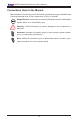
X9SPV Motherboard Series User’s Manual Conventions Used in the Manual: Special attention should be given to the following symbols for proper installation and to prevent damage done to the components or injury to yourself: Danger/Caution: Instructions to be strictly followed to prevent catastrophic system failure or to avoid bodily injury Warning: Critical information to prevent damage to the components or data loss.
Contacting Supermicro Contacting Supermicro Headquarters Address: Super Micro Computer, Inc. 980 Rock Ave. San Jose, CA 95131 U.S.A. Tel: +1 (408) 503-8000 Fax: +1 (408) 503-8008 Email: marketing@supermicro.com (General Information) support@supermicro.com (Technical Support) Web Site: www.supermicro.com Europe Address: Super Micro Computer B.V. Het Sterrenbeeld 28, 5215 ML 's-Hertogenbosch, The Netherlands Tel: +31 (0) 73-6400390 Fax: +31 (0) 73-6416525 Email: sales@supermicro.
X9SPV Motherboard Series User’s Manual Table of Contents Preface About This Manual......................................................................................................... iii About This Motherboard................................................................................................. iii Manual Organization...................................................................................................... iii Conventions Used in the Manual:......................................
Table of Contents 2-2 Motherboard Installation................................................................................... 2-2 Installation Instructions..................................................................................... 2-3 2-3 System Memory............................................................................................... 2-4 How to Install SO DIMMs................................................................................ 2-4 Memory Support.....................
X9SPV Motherboard Series User’s Manual BIOS Write Protect (JWP1)....................................................................... 2-23 CMOS Clear (JBT1).................................................................................. 2-24 USB Wake-Up (JPUSB1).......................................................................... 2-25 Watch Dog Reset (JWD1)......................................................................... 2-26 2-7 Onboard Indicators..........................................
Table of Contents Option ROM Display Messages.................................................................. 4-4 Bootup Num-Lock........................................................................................ 4-4 Wait For 'F1' If Error.................................................................................... 4-5 INT19 Trap Response................................................................................. 4-5 Watch Dog Function......................................................
X9SPV Motherboard Series User’s Manual Serial ATA Port 0~5 Hot Plug.................................................................... 4-12 Serial ATA Port 0~5 Spin Up Device......................................................... 4-12 PCIe/PCI/PnP Configuration ...................................................................... 4-12 Launch PXE, Storage, Video OpROM Policy........................................... 4-12 Other PCI device ROM priority....................................................
Table of Contents Link Speed................................................................................................ 4-23 Wake On LAN........................................................................................... 4-23 Blink LEDs (Range 0-15 seconds)............................................................ 4-23 Port Configuration Information.................................................................. 4-23 4-4 Event Logs............................................................
X9SPV Motherboard Series User’s Manual Restore User Defaults............................................................................... 4-30 Boot Override............................................................................................ 4-30 IBA IGE Slot 0100 v1381.......................................................................... 4-30 UEFI: Built-in EFI Shell............................................................................. 4-30 Me FW Image Re-Flash..........................
Chapter 1: Introduction Chapter 1 Introduction 1-1 Overview Checklist Congratulations on purchasing your computer motherboard from an acknowledged leader in the industry. Supermicro boards are designed with the utmost attention to detail and to provide you with the highest standards in quality and performance. Please check that the following items have all been included with your motherboard. If anything listed here is damaged or missing, contact your retailer.
X9SPV Motherboard Series User's Manual X9SPV-F/LN4F Image Note: All graphics and images shown in this manual were based upon the latest PCB Revision available at the time of publishing of the manual. The motherboard you've received may or may not look exactly the same as the image shown in this manual.
Chapter 1: Introduction X9SPV-F/LN4F Motherboard Layout J1 KB/MOUSE U7 U10 COM1 JCOM1 J3 COM2 JCOM2 JPUSB1 IPMI LAN1/3 JWD1 LAN2/4 JIPMB1 1 JLAN1 USB4/5 VGA LED3 MH4 JLAN2 USB8/9 UID JVGA1 LED2 U60 X9SPV-F U21 U22 MH2 FAN4 U57 JPB1 JP1 SP1 U26 U6 JL1 JOH1 FAN1 U3 JDIMM1 I-SATA4 I-SATA3 I-SATA2 I-SATA1 I-SATA0 T-SGPIO1 FAN3 I-SATA5 JDIMM2 T-SGPIO2 FAN2 JD1 LED1 F6 USB6/7 P1-DIMMA1 P1-DIMMB1 JTPM1:TPM/PORT80 MH7 JSD1:SATA DOM POWER JTPM1 JF1 JSD1 J20US
X9SPV Motherboard Series User's Manual X9SPV-F/LN4F Quick Reference (not drawn to scale) JWD1 LAN2 (TOP) KB/MOUSE (TOP) JPUSB1 LAN1 (TOP) JIPMB1 COM1 IPMI (TOP) JLAN1 J1 KB/MOUSE COM1 JCOM1 J3 COM2 JCOM2 IPMI JPUSB1 COM2 LAN1/3 LAN2/4 JWD1 LED2 JLAN2 JIPMB1 1 USB4/5 VGA LED3 JVGA1 MH4 USB8/9 UID LED3 VGA LED2 U60 U7 U21 JPB1 USB 8/9 U22 U10 LAN3 MH2 USB 4/5 FAN4 X9SPV-F LAN4 U57 FAN4 JP1 JPB1 SP1 SP1 U26 U6 JL1 JL1 JBT1 JOH1 JOH1 I-SATA4 I-SATA2 I-SATA0 3.
Chapter 1: Introduction Ports, LEDs, and Connectors Connectors/LED Description LED1 Standby Power LED IPMI Heartbeat LED Unsupported Memory LED PCI-E x16 Gen 2 Slot LED2 LED3 SLOT1 JL1 Chassis Intrusion Header JOH1 Overheat LED USB 0/1, USB 2/3 USB 6/7 USB 4/5, USB 8/9 FAN1~4 T-SGPIO1, T-SGPIO2 JPI2C1 JF1 JSD1 JTPM1 SP1 JD1 I-SATA1~I-SATA6 JPW1 DIMMA1, DIMMB1 COM1, COM2 IPMI KB/MOUSE LAN1, LAN2 LAN3, LAN4 VGA JIPMB1 CPU1 USB 3.0 Headers USB 2.
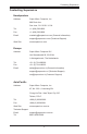
X9SPV Motherboard Series User's Manual Motherboard Features CPU Onboard, Mobile, 3rd generation Intel® Core™ i7/i5/i3 processor (FCBGA1023) Memory Two (2) SO-DIMM slots support up to 16 GB of DDR3, unbuffered, 1066/1333 MHz, ECC SO-DIMM memory Supports One DIMM per Channel DIMM sizes ECC SO-DIMM 2 GB, 4 GB and 8GB Chipset Mobile Intel® QM77 Express (3.
Chapter 1: Introduction IPMI 2.0 Nuvoton WPCM450 BMC BIOS 16 MB SPI AMI BIOS® SM Flash BIOS Plug and Play, ACPI 1.0/2.0/3.0, USB Keyboard and SMBIOS 2.3 Power ACPI/ACPM Power Management Main Switch Override Mechanism Suspend-To-RAM (STR) One (1) Disk-On-Module (DOM) Power Connector Power-on mode for AC power recovery PC Health Monitoring CPU Monitoring Onboard voltage monitors for CPU core, 1.8V, +3.3V, +5V, +/-12V, +3.
X9SPV Motherboard Series User's Manual Motherboard Features Table Model/PN X9SPV-LN4F-3QE X9SPV-LN4F-3LE X9SPV-F-3610ME X9SPV-F-3217UE Model/PN X9SPV-LN4F-3QE X9SPV-LN4F-3LE X9SPV-F-3610ME X9SPV-F-3217UE 3rd Gen IVB ECC i7-3612QE i7-3555LE i5-3610ME i3-3217UE TDP 35W 25W 35W 17W Cache 6MB 4MB 3MB 3MB Base Freq 2.1 2.5 2.7 1.6 PCIex16 Gen3 Gen3 Gen3 Gen2 1-8 Turbo (1C/DC/QC) GHz 3.1/3.0/2.8 3.2/3.1/NA 3.3/3.
Chapter 1: Introduction X9SPV Motherboard Series Block Diagram 3rd generation Intel® Core™ i7/i5/i3 Mobile processor PCIe3.0_x16 PCIe x16 SLOT 8.0GT/s SVID DDR3 (CHA) ECC-SODIMM1 1333/1067 MHz DDR3 (CHB) ECC-SODIMM2 1333/1067 MHz 5.0GT/s DMI 2.0 x4 FDI X4 IMVP 7 2x SATA PORTS SATA 6Gb/s SATA[1:0] PCIE[0] PCIe1.0_x1 2.5GT/s GLAN1 82574L RJ45 4x SATA PORTS SATA 3Gb/s SATA[5:2] PCIE[1] PCIe1.0_x1 2.5GT/s GLAN2 82574L RJ45 PCIE[2] PCIe1.0_x1 2.
X9SPV Motherboard Series User's Manual 1-2 Chipset Overview The X9SPV Motherboard Series supports a single on board, 3rd generation Intel® Core™ i7/i5/i3 processor (FCBGA1023 Mobile ECC CPU). Built around the functionality and the capability of the Intel® QM77 Express chipset, the motherboard provides substantial system performance and storage capability for performance platforms in a compact package.
Chapter 1: Introduction 1-3 PC Health Monitoring This section describes the PC health monitoring features of the X9SPV Motherboard Series. These motherboards have an onboard System Hardware Monitor chip that supports PC health monitoring. Recovery from AC Power Loss BIOS provides a setting for you to determine how the system will respond when AC power is lost and then restored to the system.
X9SPV Motherboard Series User's Manual 1-4 Power Configuration Settings This section describes features of your motherboard that deal with power and power settings. Slow Blinking LED for Suspend-State Indicator When the CPU goes into a suspend state, the chassis power LED will start blinking to indicate that the CPU is in suspend mode. When the user presses any key, the CPU will wake up and the LED will automatically stop blinking and remain on.
Chapter 1: Introduction 1-6 Super I/O The Super I/O provides two high-speed, 16550 compatible serial communication ports (UARTs). Each UART includes a 16-byte send/receive FIFO, a programmable baud rate generator, complete modem control capability and a processor interrupt system. Both UARTs provide legacy speed with baud rate of up to 115.2 Kbps as well as an advanced speed with baud rates of 250 K, 500 K, or 1 Mb/s, which support higher speed modems.
X9SPV Motherboard Series User's Manual Notes 1-14
Chapter 2: Installation Chapter 2 Installation 2-1 Static-Sensitive Devices Electrostatic-Discharge (ESD) can damage electronic components. To prevent damage to your system board, it is important to handle it very carefully. The following measures are generally sufficient to protect your equipment from ESD. Precautions • Use a grounded wrist strap designed to prevent static discharge. • Touch a grounded metal object before removing the board from the antistatic bag.
X9SPV Motherboard Series User's Manual 2-2 Motherboard Installation All motherboards have standard mounting holes to fit different types of chassis. Make sure that the locations of all the mounting holes for both motherboard and chassis match. Although a chassis may have both plastic and metal mounting fasteners, metal ones are highly recommended because they ground the motherboard to the chassis. Make sure that the metal standoffs click in or are screwed in tightly.
Chapter 2: Installation Caution: To avoid damaging the motherboard and its components, please do not use a force greater than 8 lb/inch on each mounting screw during motherboard installation. 1 Installation Instructions Install the I/O shield into the chassis. I/O Shield 2 3 Locate the mounting holes on the motherboard. Refer to the layout on the previous page for mounting hole locations. Locate the matching mounting holes on the chassis. Install standoffs in the chassis as needed.
X9SPV Motherboard Series User's Manual 2-3 System Memory CAUTION Exercise extreme care when installing or removing DIMM modules to prevent any possible damage. Note: Check the Supermicro website for a list of memory modules that have been validated with the X9SPV motherboard series. How to Install SO DIMMs 1. Insert the desired number of SO DIMMs into the memory slots, starting with DIMMA1, then DIMMB1.
Chapter 2: Installation The SO DIMM Socket 1 Position the SO DIMM module's bottom key so it aligns with the receptive point on the slot. Take note of the module's side notches and the locking clips on the socket. 2 Insert the SO DIMM module straight down. 3 Press down until the module locks into place. The side clips will automatically secure the SO DIMM module, locking it into place. 4 To Remove: Use your thumbs to gently push the side clips near both ends away from the module.
X9SPV Motherboard Series User's Manual 2-4 Connectors/I/O Ports The I/O ports are color coded in conformance with the PC 99 specification. See the figure below for the colors and locations of the various I/O ports.
Chapter 2: Installation PS/2 KB/Mouse Port (KB/Mouse) The PS/2 keyboard/mouse port is located above the Back Panel USB Ports 8/9 on the motherboard. See the table at right for pin definitions. PS/2 KB/Mouse Pin Definitions (JF1) Pin# Definition 1 KB Data 2 MS Data 3 Ground 4 Vcc 5 KB CLK 6 MS CLK Note: This motherboard offers three Keyboard/Mouse connection options as shown in the graphic below. • • • 1. Connect a keyboard cable or a mouse cable to the PS2 KB/Mouse port. 2.
X9SPV Motherboard Series User's Manual Universal Serial Bus (USB) Back Panel USB Type A USB 10 Pin Definitions Four Universal Serial Bus ports (USB 4/5, 8/9) are located on the I/O backpanel. Pin# Definition Additionally, one USB 2.0 header (USB 6/7) and two USB 3.0 headers (USB 0/1, 2/3) are also located on the motherboard to provide front chassis access. (Cables are not included). See the tables on the right for pin definitions.
Chapter 2: Installation Serial Ports (COM1/COM2) Serial Ports-COM1/COM2/COM3/COM4 Pin Definitions Two COM connections (COM1, COM2) are located on the motherboard. COM1 Pin # is located on the back I/O panel. A COM2 header is also located just behind the COM1 port to provide an additional onboard serial port. See the table on the right for pin definitions.
X9SPV Motherboard Series User's Manual VGA Connector (VGA) VGA Port/Connector Pin Definitions A VGA connector is located next to the LAN Ports on the I/O back panel. This connector is used to provide video display. Refer to the board layout below for the location.
Chapter 2: Installation LAN Ports (LAN1~LAN4) RJ45/LAN Pin Definitions Two gigabit LAN ports are located on the I/O back panel (four on the X9SPV- Pin # LN4F). These ports accept RJ45 type cables. These are used to connect the motherboard to a network. On product models X9SPV-F and X9SPV-LN4F, an IPMI port is also provided for remote management through a TCP/IP network.
X9SPV Motherboard Series User's Manual Front Control Panel JF1 contains header pins for various buttons and indicators that are normally located on a control panel at the front of the chassis. These connectors are designed specifically for use with Supermicro server chassis. See the figure below for the descriptions of the various control panel buttons and LED indicators. Refer to the following section for descriptions and pin definitions.
Chapter 2: Installation Front Control Panel Pin Definitions Power LED Power LED Pin Definitions (JF1) The Power LED connection is located on pins 15 and 16 of JF1. Refer to the table on the right for pin definitions. Pin# Definition 15 +3.3V 16 Ground HDD LED HDD LED Pin Definitions (JF1) The HDD LED connection is located on pins 13 and 14 of JF1. Attach a hard drive LED cable here to display disk activity (for any hard drive activities on the system, including Serial ATA and IDE).
X9SPV Motherboard Series User's Manual Overheat (OH)/Fan Fail LED OH/Fan Fail Indicator Status Connect an LED Cable to the OH/Fan Fail connection on pins 7 and 8 of JF1 State to provide advanced warnings of chassis overheat or fan failure. Refer to the table on the right for pin definitions. Definition Off Normal On Overheat Flashing Fan Fail Power Fail LED Pin Definitions (JF1) Power Fail LED The Power Fail LED connection is located on pins 5 and 6 of JF1.
Chapter 2: Installation Reset Button Reset Button Pin Definitions (JF1) The Reset Button connection is located on pins 3 and 4 of JF1. Attach it to a hardware reset switch on the computer case. Refer to the table on the right for pin definitions. Pin# Definition 3 Reset 4 Ground Power Button Pin Definitions (JF1) Power Button The Power Button connection is located on pins 1 and 2 of JF1. Momentarily contacting both pins will power on/off the system.
X9SPV Motherboard Series User's Manual 2-5 Connecting Cables This section provides brief descriptions and pin-out definitions for onboard power connectors. Be sure to use the correct cable for each header or connector. ATX Power Connector (JPW1) ATX Power 24-pin Connector Pin Definitions (JPW1) The 24-pin power connector is used to provide power to the motherboard. This connector meets the SSI EPS 12V specification. See the tables on the right for pin definitions.
Chapter 2: Installation Fan Headers The X9SPV Motherboard Series has three fan headers (Fan1~Fan3). These Fan Header Pin Definitions fans are 4-pin fan headers. Although Pins 1~3 of the fan headers are backward compatible with the traditional 3-pin fans, please 4-pin fans on the motherboard to enable the motherboard to control fan speed through the BIOS. Refer to the table on the right for pin definitions.
X9SPV Motherboard Series User's Manual Chassis Intrusion (JL1) Chassis Intrusion Pin Definitions (JL1) A Chassis Intrusion header is located at JL1 on the motherboard. Attach the appropriate cable from the chassis to inform you of a chassis intrusion when the chassis is opened.
Chapter 2: Installation SATA DOM Power (JSD1) SATA DOM Power Pin Definitions The SATA DOM Power on JSD1 is used to supply power to SATA Disk-on-Module (DOM) solid-state storage devices. Pin# Definition 1 +5V 2 Ground 3 Ground Power SMB I2C Connector (JPI2C1) Power System Management Bus (I2C) connector enables monitoring the status of the power supply, fan and system temperature. See the table on the right for pin definitions.
X9SPV Motherboard Series User's Manual T-SGPIO Headers (T-SGPIO1/2) Serial_Link-SGPIO Pin Definitions The T-SGPIO1 and T-SGPIO2 (SerialLink General Purpose Input/Output) headers are located near the SATA connectors on the motherboard. These headers are used to communicate with the enclosure management chip in the system. See the table on the right for pin definitions. Refer to the board layout below for the locations of the headers.
Chapter 2: Installation Power LED/Speaker (JD1) On the JD1 header, pins 1~3 are used for a power LED and pins 4~7 are used for an external speaker. If you wish to use the onboard speaker, you should close pins 6-7 with a jumper. See the table on the right for speaker pin definitions.
X9SPV Motherboard Series User's Manual 2-6 Jumper Settings Explanation of Jumpers To modify the operation of the motherboard, jumpers can be used to choose between optional settings. Jumpers create shorts between two pins to change the function of the connector. Pin 1 is identified with a square solder pad on the printed circuit board. Note: On two pin jumpers, "Closed" means the jumper is on and "Open" means the jumper is off the pins.
Chapter 2: Installation BMC Enable/Disable (JPB1) BMC IPMI Enable/Disable Jumper Settings JPB1 is used to enable or disable the BMC (Baseboard Management Control) chip and the onboard IPMI connection. This jumper is used together with the IPMI settings in the BIOS. See the table on the right for jumper settings. Supported on both the X9SPV-F and X9SPV-LN4F.
X9SPV Motherboard Series User's Manual CMOS Clear (JBT1) JBT1 is used to clear CMOS. Instead of pins, this "jumper" consists of contact pads to prevent accidental clearing of CMOS. To clear CMOS, use a metal object such as a small screwdriver to touch both pads at the same time to short the connection. Always remove the AC power cord from the system before clearing CMOS.
Chapter 2: Installation USB Wake-Up (JPUSB1) USB Wake-Up Jumper Settings Use the JPUSB1 jumper to enable system "wake-up" via a USB device. This jumper allows you to "wake-up" the system by pressing a key on the USB keyboard or by clicking the USB mouse of your system. The JPUSB1 jumper is used together with the USB Wake-Up function in the BIOS. Enable both the jumper and the BIOS setting to activate this function. See the table on the right for jumper settings and jumper connections.
X9SPV Motherboard Series User's Manual Watch Dog Reset (JWD1) Watch Dog Jumper Settings Watch Dog (JWD1) is a system monitor that can reboot the system when a software ap- Jumper Setting plication hangs. Close pins 1~2 to reset the system if an application hangs. Close pins 2~3 to generate a non-maskable interrupt signal for the application that hangs. See the table on the right for jumper settings. Watch Dog must also be enabled in the BIOS.
Chapter 2: Installation 2-7 Onboard Indicators GLAN Link/Speed LED Indicator LAN Port LEDs Two LAN ports are located on the I/O Backpanel. Each Ethernet LAN port has two LEDs. The yellow Activity LED (right, see below) indicates activity, while the Link/ Speed LED (left) may be green, amber or off to indicate the speed of the connection. See the tables at right for more information.
X9SPV Motherboard Series User's Manual Standby Power LED (LED1) Onboard PWR LED (LED1) LED Status An Onboard Power LED is located at LED1 on the motherboard. When LED1 Status is on, the AC power cable is connected and the power supply hard switch is on. The system may be on standby or running. Definition Off System Off (Soft Switch) On Power is Detected IPMI Heartbeat LED (LED2) LED Settings IPMI Heartbeat LED (LED2) An IPMI Heartbeat LED is located at LED2.
Chapter 2: Installation 2-8 Serial ATA and HDD Connections Note the following conditions when connecting the Serial ATA and hard disk drive cables: • Be sure to use the correct cable for each connector. Refer to Page 1-1 for cables that came with your shipment. SATA Connections (SATA1~SATA6) Two Serial ATA (SATA) 3.0 connectors (I-SATA 0/1) are located on the motherboard. In addition, four SATA 2.0 (I-SATA 2~5) connectors are also located on the board. The SATA 3.
X9SPV Motherboard Series User's Manual Notes 2-30
Chapter 3: Troubleshooting Chapter 3 Troubleshooting 3-1 Troubleshooting Procedures Use the following procedures to troubleshoot your system. If you have followed all of the procedures below and still need assistance, refer to the ‘Technical Support Procedures’ and/or ‘Returning Merchandise for Service’ section(s) in this chapter. Always disconnect the AC power cord before adding, changing or installing any hardware components. Before Power On 1.
X9SPV Motherboard Series User's Manual 2. Use the speaker to determine if any beep codes exist. (Refer to Appendix A for details on beep codes.) 3. Remove all memory modules and turn on the system. (If the alarm is on, check the specs of memory modules, reset the memory or try a different one.) Memory Errors 1. Make sure that the ECC SO-DIMM modules are properly installed and fully seated in the slots. 2. Please check Section 2-3 and make sure that you are using the correct memory.
Chapter 3: Troubleshooting Note: Not all BIOS can be flashed. Some cannot be flashed; it depends on the modifications to the boot block code. 3.
X9SPV Motherboard Series User's Manual BIOS warning message and the information on how to update your BIOS on our web site. Select your motherboard model and download the BIOS (.rom) file to your computer. Also, check the current BIOS revision and make sure that it is newer than your BIOS before downloading. You may choose the zip file or the .exe file. If you choose the zipped BIOS file, please unzip the BIOS file onto a bootable device or a USB pen/thumb drive.
Chapter 3: Troubleshooting 3-4 Returning Merchandise for Service A receipt or copy of your invoice marked with the date of purchase is required before any warranty service will be rendered. You can obtain service by calling your vendor for a Returned Merchandise Authorization (RMA) number. When returning to the manufacturer, the RMA number should be prominently displayed on the outside of the shipping carton, and mailed prepaid or hand-carried.
X9SPV Motherboard Series User's Manual Notes 3-6
Chapter 4: AMI BIOS Chapter 4 BIOS 4-1 Introduction This chapter describes the AMI BIOS Setup Utility for the X9SPV-F/LN4F Motherboard. The AMI ROM BIOS is stored in a Flash EEPROM and can be easily updated. This chapter describes the basic navigation of the AMI BIOS Setup Utility setup screens. Note: For instructions on BIOS recovery, please refer to the instruction guide posted at http://www.supermicro.com/support/manuals/.
X9SPV-F/LN4F Motherboard User Manual How to Start the Setup Utility Normally, the only visible Power-On Self-Test (POST) routine is the memory test. As the memory is being tested, press the key to enter the main menu of the AMI BIOS Setup Utility. From the main menu, you can access the other setup screens. An AMI BIOS identification string is displayed at the left bottom corner of the screen, below the copyright message. Warning! Do not upgrade the BIOS unless your system has a BIOS-related issue.
Chapter 4: AMI BIOS System Overview: The following BIOS information will be displayed: System Time/System Date Use this option to change the system time and date. Highlight System Time or System Date using the arrow keys. Enter new values through the keyboard. Press the key or the arrow keys to move between fields. The date must be entered in Day MM/DD/YY format. The time is entered in HH:MM:SS format. (Note: The time is in the 24-hour format. For example, 5:30 P.M. appears as 17:30:00.
X9SPV-F/LN4F Motherboard User Manual 4-3 Advanced Setup Configurations Use the arrow keys to select Boot Setup and hit to access the submenu items: BOOT Feature Quiet Boot This option allows the bootup screen options to be modified between POST messages or the OEM logo. Select Disabled to display the POST messages. Select Enabled to display the OEM logo instead of the normal POST messages. The options are Enabled and Disabled.
Chapter 4: AMI BIOS Wait For 'F1' If Error This forces the system to wait until the 'F1' key is pressed if an error occurs. The options are Disabled and Enabled. INT19 Trap Response The Interrupt 19 (INT19) feature determines how the BIOS will react to INT19 trapping by Option ROM. If set to Immediate, BIOS will execute the trap right away. If set to Postponed, BIOS will execute the trap during legacy boot.
X9SPV-F/LN4F Motherboard User Manual Active Processor Cores Set to Enabled to use a processor's Second Core and beyond. (Please refer to Intel's web site for more information.) The options are All, 1, 2, and 3. Limit CPUID Maximum This feature allows the user to set the maximum CPU ID value. Enable this function to boot the legacy operating systems that cannot support processors with extended CPUID functions. The options are Enabled and Disabled (for the Windows OS.).
Chapter 4: AMI BIOS CPU PPM Configuration Power Technology This feature determines what power-saving scheme the motherboard uses. The options are Disabled, Energy Efficient and Custom. If Custom is selected, the following options become available: EIST EIST (Enhanced Intel SpeedStep Technology) allows the system to automatically adjust processor voltage and core frequency in an effort to reduce power consumption and heat dissipation. Please refer to Intel’s web site for detailed information.
X9SPV-F/LN4F Motherboard User Manual Advanced Chipset Control WARNING: Setting the wrong values in the following sections may cause the system to malfunction. System Agent (SA) Configuration This submenu allows you to configure System Agent Parameters. Memory Configuration This section displays memory status such as memory speed and total memory. Memory Frequency Limiter Use this item to select the maximum memory frequency (in Mhz).
Chapter 4: AMI BIOS PEG0 ASPM Set this item to control ASPM (Active State Power Management) support for PEG: Device 1 Function 0. The options are Disabled, Auto, ASPM L0s, ASPM L1, and ASPM L0sL1. Enable PEG Use this feature to enable the PEG. The options are Disabled, Enabled, and Auto. De-emphasis Control This item sets the De-emphasis control on PEG. The options are -6 dB and -3.5 dB. Initiate Graphic Adapter Use this feature to select which device will operate as the primary display.
X9SPV-F/LN4F Motherboard User Manual EHCI Hand-Off This item is for Operating Systems that do not support Enhanced Host Controller Interface (EHCI) hand-off. When enabled, EHCI ownership change will be claimed by the EHCI driver. The settings are Enabled and Disabled. XHCI Pre-Boot Driver This feature enables support for the xHCI pre-boot driver. The options are Enabled and Disabled. XHCI Mode Use this feature to select the xHCI controller mode of operation.
Chapter 4: AMI BIOS SLP_S4 Assertion Width Use this feature to select a minimum assertion width of the SLP_S4 signal. The options are Disabled, 1-2 Seconds, 2-3 Seconds, 3-4 Seconds, and 4-5 Seconds. IDE/SATA Configuration When this submenu is selected, the AMI BIOS automatically detects the presence of the SATA Devices and displays the following items: SATA Controllers This item enables or disables the on board SATA controller.
X9SPV-F/LN4F Motherboard User Manual RAID Mode The following items are displayed when RAID Mode is selected: Serial ATA Port 0~5 Hot Plug Set this item to Enabled to enable hot-plugging for the particular port. The options are Enabled and Disabled. Serial ATA Port 0~5 Spin Up Device Set this item to Enabled to enable device spin-up support. The options are Enabled and Disabled.
Chapter 4: AMI BIOS Maximum Payload This feature selects the setting for the PCIE maximum payload size. The options are Auto, 128 Bytes, and 256 Bytes, 512 Bytes, 1024 Bytes, 2048 Bytes, and 4096 Bytes. Maximum Read Request This feature selects the setting for the PCIE maximum Read Request size. The options are Auto, 128 Bytes, 256 Bytes, 512 Bytes, 1024 Bytes, 2048 Bytes, and 4096 Bytes. Above 4G Decoding Set this item to Enabled to activate 64-bit capable devices to be decoded above the 4G address space.
X9SPV-F/LN4F Motherboard User Manual Maximum Read Request This feature selects the setting for the PCI Express maximum Read Request size. The options are Auto, 128 Bytes, 256 Bytes, 512 Bytes, 1024 Bytes, 2048 Bytes, and 4096 Bytes. ASPM Support Set this item to the desired ASPM (Active State Power Management) level. The options are Disabled, Auto and Force L0s. Extended Synch Select Enabled for Extended Synchronization support, which will extend the same synchronization patterns for the PCI-E device.
Chapter 4: AMI BIOS Configuration Request, permitting access to Extended Functions in an ARI device immediately below the port. The options are Disabled and Enabled. AtomicOp Requester Enable (Available when supported by the hardware) When set to Enabled, this feature initiates AtomicOp requests only if Bus Master Enable bit is in the Command Register set. The options are Disabled and Enabled.
X9SPV-F/LN4F Motherboard User Manual Compliance SOS (Available when supported by the hardware) When set to Enabled, this feature will force LTSSM to send SKP ordered sets between sequences when sending compliance pattern or modified compliance pattern. The options are Disabled and Enabled.
Chapter 4: AMI BIOS Ipv6 PXE Support This feature enables Ipv6 boot support. If disabled, an Ipv6 PXE boot option will not be created. The options are Enabled and Disabled. Super IO Device Configuration Serial Port 1 Configuration / Serial Port 2 Configuration Serial Port 1 / Serial Port 2 Select Enabled to enable the onboard serial port. The options are Enabled and Disabled.
X9SPV-F/LN4F Motherboard User Manual Remote Access Configuration COM1, COM2, SOL Console Redirection Use this feature to enable console redirection for COM1, and COM2 ports. The options are Enabled and Disabled. The default for COM1 and COM2 is Disabled. The default for SOL is Enabled. Console Redirection Settings This feature allows the user to specify how the host computer will exchange data with the client computer, which is the remote computer used by the user.
Chapter 4: AMI BIOS Flow Control This feature allows the user to set the flow control for Console Redirection to prevent data loss caused by buffer overflow. Send a "Stop" signal to stop sending data when the receiving buffer is full. Send a "Start" signal to start sending data when the receiving buffer is empty. The options are None and Hardware RTS/CTS. VT-UTF8 Combo Key Support Select Enabled to enable VT-UTF8 Combination Key support for ANSI/VT100 terminals. The options are Enabled and Disabled.
X9SPV-F/LN4F Motherboard User Manual Console Redirection Settings (for EMS) This feature allows the user to specify how the host computer will exchange data with the client computer, which is the remote computer used by the user. Out-of-Band-Mgmt Port Use this feature to select the port for out-of-band management. The options are COM1, COM2, and SOL. Terminal Type This feature allows the user to select the target terminal emulation type for Console Redirection.
Chapter 4: AMI BIOS ACPI Sleep State This setting allows you to configure the ACPI (Advanced Configuration and Power Interface) sleep state for your system when it is in the Suspend mode. The options are Suspend Disabled, S1 only (CPU Stop Clock), S3 only (Suspend to RAM), and Both S1 and S3 available for OS to choose from. S3 (Suspend to RAM) is the deepest sleep state in these options. PS2 KB/MS Wake up Use this feature to select the PS2 Keyboard/Mouse wake up setting.
X9SPV-F/LN4F Motherboard User Manual Add an Attempt The settings on this section are setup parameters to connect to a remote iSCSI device. iSCSI Attempt Name - assigns a unique name to this attempt. iSCSI Mode - select Enabled or Disabled Connection Retry Count - if the initial connection fails or times out, this is how many times an attempt will be made to connect. Connection Establishing Timeout - This is the time in milliseconds the system will wait for a connection until it times out.
Chapter 4: AMI BIOS Intel(R) 82579LM / Intel(R) 82574L Gigabit Network Connection NIC Configuration Link Speed Use this feature to select the link speed to be used. The options are AutoNeg, 10 Mbps Half, 10 Mbps Full, 100 Mbps Half and 100 Mbps Full. Wake On LAN Use this feature to activate the Wake On LAN (WOL) feature. The options are Enabled, and Disabled. Blink LEDs (Range 0-15 seconds) Please specifies the blink rate of the NIC LED. Select from 1-15 second intervals.
X9SPV-F/LN4F Motherboard User Manual Change SmBIOS Event Log Settings Smbios Event Log Change this item to enable or disable all features of the Smbios Event Logging during boot. The options are Enabled and Disabled. Erase Event Log This option erases all logged events. The options are No, Yes, Next reset and Yes, Every reset. When Log is Full This option automatically clears the Event Log memory of all messages when it is full. The options are Do Nothing and Erase Immediately.
Chapter 4: AMI BIOS 4-5 IPMI Settings Intelligent Platform Management Interface (IPMI) is a set of common interfaces that IT administrators can use to monitor system health and to manage the system as a whole. For more information on the IPMI specifications, please visit Intel's website at www.intel.com. System Event Log This feature is used to change the System Event Log (SEL) configuration. SEL Components - Change this item to enable or disable all features of System Event Logging.
X9SPV-F/LN4F Motherboard User Manual Log EFI Status Codes This option enables or disables the logging of Extensible Firmware Interface (EFI) status codes. The options are Disabled, and Enabled. BMC Network Configuration Set this feature to configure the IPMI LAN adapter with a network address. Update IPMI LAN Configuration This feature allows the user to decide if the BIOS should configure the IPMI setting at next system boot. The options are No and Yes.
Chapter 4: AMI BIOS 4-6 Boot Use this feature to configure Boot Settings: Setup Prompt Timeout Use this feature to enter the number of seconds to wait for setup activation key. The default setting is 1 second. Boot Options Priorities This feature allows the user to specify which devices are boot devices and the order of priority from which the system boots during startup. Boot Option #1, Boot option #2, Boot Option #3, etc The settings are [any detected boot device] and Disabled.
X9SPV-F/LN4F Motherboard User Manual 4-7 Security Settings • If the Administrator password is defined ONLY - this controls access to the BIOS setup ONLY. • If the User's password is defined ONLY - this password will need to be entered during each system startup or boot, and will also have Administrator rights in the setup. • Passwords must be at least 3 and up to 20 characters long. Administrator Password Press Enter to create a new, or change an existing Administrator password.
Chapter 4: AMI BIOS 4-8 Exit Select the Exit tab from the BIOS Setup Utility screen to enter the Exit BIOS Setup screen. Discard Changes and Exit Select this option to quit the BIOS Setup without making any permanent changes to the system configuration, and reboot the computer. Select Discard Changes and Exit from the Exit menu and press .
X9SPV-F/LN4F Motherboard User Manual Restore Defaults To set this feature, select Restore Defaults from the Exit menu and press . These are factory settings designed for maximum system stability, but not for maximum performance. Save As User Defaults To set this feature, select Save as User Defaults from the Exit menu and press .
Appendix A: POST Error Beep Codes Appendix A POST Error Beep Codes This section lists POST (Power On Self Test) error beep codes for the AMI BIOS. POST error beep codes are divided into two categories: recoverable and terminal. This section lists Beep Codes for recoverable POST errors. Recoverable POST Error Beep Codes When a recoverable type of error occurs during POST, BIOS will display a POST code that describes the problem.
X9SPV Motherboard Series User's Manual Notes A-2
X9SPV Motherboard Series User's Manual Appendix B Software Installation Instructions B-1 Installing Drivers Additional drivers and tools for your motherboard are available for download at the Supermicro website. To install these software programs and drivers, run the application and a screen will appear as below. Click the icons to the right of these items. Driver/Tool Installation Display Screen Note: Click the icons showing a hand writing on the paper to view the readme files for each item.
X9SPV Motherboard Series User's Manual B-2 Configuring Supero Doctor III The Supero Doctor III program is a Web-base management tool that supports remote management capability. It includes Remote and Local Management tools. The local management is called the SD III Client. The Supero Doctor III program included on the CDROM that came with your motherboard allows you to monitor the environment and operations of your system.
X9SPV Motherboard Series User's Manual Supero Doctor III Interface Display Screen-II (Remote Control) Note: SD III Software Revision 1.0 can be downloaded from our Web site at: ftp://ftp.supermicro.com/utility/Supero_Doctor_III/. You can also download SDIII User's Guide at: http://www.supermicro.com/PRODUCT/ Manuals/SDIII/UserGuide.pdf. For Linux, we will still recommend that you use Supero Doctor II.
X9SPV Motherboard Series User's Manual Notes B-4
Appendix C: UEFI BIOS Recovery Appendix C UEFI BIOS Recovery Instructions Warning! Do not upgrade the BIOS unless your system has a BIOS-related issue. Flashing the wrong BIOS can cause irreparable damage to the system. In no event shall Supermicro be liable for direct, indirect, special, incidental, or consequential damages arising from a BIOS update. If you need to update the BIOS, do not shut down or reset the system while the BIOS is updating to avoid possible boot failure.
X9SPV Motherboard Series User’s Manual a USB CD/DVD ROM/RW device can be used for this purpose. However, a USB Hard Disk drive cannot be used for BIOS recovery at this time. To perform UEFI BIOS recovery using a USB-attached device, follow the instructions below. 1. Using a different machine, copy the "Super.ROM" binary image file into the disc Root "\" Directory of a USB device or a writeable CD/DVD. Note: If you cannot locate the "Super.ROM" file in your driver disk, visit our website at www.supermicro.
Appendix C: UEFI BIOS Recovery 5. When the screen as shown above displays, using the arrow key, select the item- "Proceed with flash update" and press the key. You will see the progress of BIOS Recovery as shown in the screen below. Note: Do not interrupt the process of BIOS flashing until it is completed. 6. After the process of BIOS Recovery is complete, press any key to reboot the system. 7. Using a different system, extract the BIOS package into a bootable USB flash drive.
X9SPV Motherboard Series User’s Manual 8. When a DOS prompt appears, enter AMI.BAT BIOSname.### at the prompt. Note: Do not interrupt this process until BIOS flashing is completed. 9. After seeing the message that BIOS update is completed, unplug the AC power cable from the power supply to clear CMOS, and then plug the AC power cable in the power supply again to power on the system. 10. Press continuously to enter the BIOS Setup utility. 11. Press to load default settings. 12.
Disclaimer The products sold by Supermicro are not intended for and will not be used in life support systems, medical equipment, nuclear facilities or systems, aircraft, aircraft devices, aircraft/emergency communication devices or other critical systems whose failure to perform be reasonably expected to result in significant injury or loss of life or catastrophic property damage.