
User's Manual

5-14
SUPERSERVER 5016T-TB User's Manual
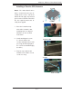
Reset Button
The reset button (from the computer
chassis) connects to pins 3 and 4 of
JF1. See the table on the right for pin
defi nitions.
Power Button
The power button (from the computer
chassis) connects to pins 1 and 2 of
JF1. See the table on the right for pin
defi nitions.
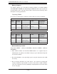
5-9 Connector Defi nitions
Required Connection
+12V 8-pin Power
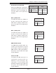
Pin Defi nitions (JPW2)
Pins Defi nition
1 - 4 Ground
5 - 8 +12V
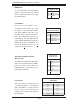
ATX Power 24-pin Connector
Pin Defi nitions (JPW1)
Pin# Defi nition Pin # Defi nition
13 +3.3V 1 +3.3V
14 -12V 2 +3.3V
15 COM 3 COM
16 PS_ON 4 +5V
17 COM 5 COM
18 COM 6 +5V
19 COM 7 COM
20 Res (NC) 8 PWR_OK
21 +5V 9 5VSB
22 +5V 10 +12V
23 +5V 11 +12V
24 COM 12 +3.3V
Reset Button
Pin Defi nitions (JF1)
Pin# Defi nition
3 Reset
4 Ground
Power Button
Pin Defi nitions (JF1)
Pin# Defi nition
1 Power Signal
2 Ground
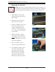
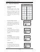
Processor Power Connector
JPW2 must also be connected to the
power supply to provide power for the
processor. See the table on the right
for pin defi nitions.
Main ATX Power Supply
Connector
The 24-pin primary power supply
connector (JPW1) meets the SSI
EPS 12V specification. The 8-pin
CPU PWR connector (JPW2) is also
required for the processor. Refer
to the table on the right for the pin
defi nitions.
Power Fail LED
The Power Fail LED connection is
located on pins 5 and 6 of JF1. Re-
fer to the table on the right for pin
defi nitions.
PWR Fail LED
Pin Defi nitions (JF1)
Pin# Defi nition
5 Vcc
6 Ground