
User's Manual

1-6
X9DRG-HF/X9DRG-HTF Motherboard User’s Manual
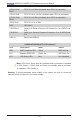
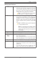
LED Description State Status
DM1 BMC Heartbeat LED Green BMC Normal
LE1 Standby PWR LED Green: On SB Power On
LE4 UID Switch LED Blue Unit Identied
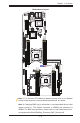
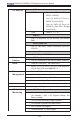
Note: CPU1 Slot1, Slot2, Slot5 are available when a processor is installed
in CPU Socket 1. CPU2 Slot3 and Slot4 are available when a processor
is installed in CPU Socket 2.
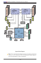
Warning: To provide adequate power supply to the system, be sure to connect all
onboard power connectors to the power supply.
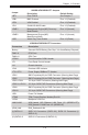
(CPU1) Slot1/
Slot2
PCI-E 3.0 x16 Slots (Available when CPU1 is populated)
(CPU1) Slot5 PCI-E 3.0 x8 in x16 Slot (Available when CPU1 is populated)
(CPU2) Slot3/
Slot4
PCI-E 3.0 x16 Slots (Available when CPU2 is populated)
(PCH) Slot6 PCI-E 2.0 x4 in x8 Slot
SW1 UID Switch
T-SGPIO1/2 Serial_Link General Purpose I/O Headers 0/1 for I-SATA Ports
0~5
T-SGPIO-S Serial_Link General Purpose I/O Header -S for S-SATA Ports
0~3
USB 0/1 Back Panel USB 0/1
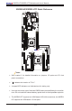
X9DRG-HF/X9DRG-HTF LED Indicators