SUPER SUPERSERVER 1018D-73MTF USER’S MANUAL 1.
The information in this User’s Manual has been carefully reviewed and is believed to be accurate. The vendor assumes no responsibility for any inaccuracies that may be contained in this document, makes no commitment to update or to keep current the information in this manual, or to notify any person or organization of the updates. Please Note: For the most up-to-date version of this manual, please see our web site at www.supermicro.com. Super Micro Computer, Inc.
Preface Preface About This Manual This manual is written for professional system integrators and PC technicians. It provides information for the installation and use of the SuperServer 1018D-73MTF. Installation and maintenance should be performed by experienced technicians only. The SuperServer 1018D-73MTF is a high-end server based on the SC113MTQ330CB 1U rackmount chassis and the Super X10SL7-F processor motherboard.
SUPERSERVER 1018D-73MTF User's Manual Chapter 5: Advanced Motherboard Setup Chapter 5 provides detailed information on the X10SL7-F motherboard, including the locations and functions of connections, headers and jumpers. Refer to this chapter when adding or removing processors or main memory and when reconfiguring the motherboard. Chapter 6: Advanced Chassis Setup Refer to Chapter 6 for detailed information on the SC113MTQ server chassis.
Preface Notes v
SUPERSERVER 1018D-73MTF User's Manual Table of Contents Chapter 1 Introduction 1-1 Overview ......................................................................................................... 1-1 1-2 Motherboard Features ..................................................................................... 1-2 Processors ...................................................................................................... 1-2 Memory ..................................................................
Table of Contents 3-2 Control Panel Buttons ..................................................................................... 3-1 Reset ............................................................................................................... 3-1 Power .............................................................................................................. 3-1 UID ..................................................................................................................
SUPERSERVER 1018D-73MTF User's Manual 5-5 Installing Memory ............................................................................................ 5-7 Memory Population Guidelines ....................................................................... 5-8 5-6 Adding PCI Cards ........................................................................................... 5-9 5-7 Motherboard Details ......................................................................................
Chapter 1: Introduction Chapter 1 Introduction 1-1 Overview The SuperServer 1018D-73MTF is a high-end server comprised of two main subsystems: the SC113MTQ-330CB 1U server chassis and the X10SL7-F single processor motherboard. Please refer to our web site for information on operating systems that have been certified for use with the system (www.supermicro.com).
SUPERSERVER 1018D-73MTF User's Manual 1-2 Motherboard Features At the heart of the SuperServer 1018D-73MTF lies the X10SL7-F, a single processor motherboard based on Intel's C222 chipset. Below are the main features of the X10SL7-F (see Figure 1-1 for a block diagram of the chipset). Processors The X10SL7-F supports a single Intel® Xeon® E3-1200 v3 or a 4th Generation Core i3/ i5/ i7 processor in an LGA1150 socket.
Chapter 1: Introduction 1-3 Server Chassis Features The SC113MTQ-330CB is a short depth (20") 1U chassis that features eight 2.5" hard drive bays and a high-efficiency power supply. The following is a general outline of the main features of the SC113MTQ-330CB chassis. System Power When configured as the SuperServer 1018D-73MTF, the SC113MTQ-330CB chassis includes a single 330W high-efficiency power supply.
SUPERSERVER 1018D-73MTF User's Manual Figure 1-1. Intel C222 Chipset: System Block Diagram Note: This is a general block diagram. Please see Chapter 5 for details. PCIe x16 SLOT LSI 2308 SAS2 6.0Gbps PCIe3.0_x8 8.0Gb Intel i3/i5/i7 Processor (H3) PCIe3.0_x8 DDR3 (CHA) 1600/1333MHz DDR3 (CHB) 1600/1333MHz DIMM1 DIMM2(Far) DIMM1 DIMM2(Far) 8.0Gb SVID 8 SAS PORTS 4 SATA PORTS 2 SATA PORTS PCIe_x4 PCIe_x1 5.0Gbps 2.5Gbps PCIe_x1 SATA-II 3.0Gbps SATA-III USB3.0 6 USB PORTS USB2.
Chapter 1: Introduction 1-4 Contacting Supermicro Headquarters Address: Super Micro Computer, Inc. 980 Rock Ave. San Jose, CA 95131 U.S.A. Tel: +1 (408) 503-8000 Fax: +1 (408) 503-8008 Email: marketing@supermicro.com (General Information) support@supermicro.com (Technical Support) Web Site: www.supermicro.com Europe Address: Super Micro Computer B.V. Het Sterrenbeeld 28, 5215 ML 's-Hertogenbosch, The Netherlands Tel: +31 (0) 73-6400390 Fax: +31 (0) 73-6416525 Email: sales@supermicro.
SUPERSERVER 1018D-73MTF User's Manual Notes 1-6
Chapter 2: Server Installation Chapter 2 Server Installation 2-1 Overview This chapter provides a quick setup checklist to get your SuperServer 1018D-73MTF up and running. Following these steps in the order given should enable you to have the system operational within a minimum amount of time. This quick setup assumes that your SuperServer 1018D-73MTF system has come to you with the processors and memory preinstalled.
SUPERSERVER 1018D-73MTF Manual • This product is not suitable for use with visual display work place devices acccording to §2 of the the German Ordinance for Work with Visual Display Units. 2-4 Warnings and Precautions Rack Precautions • Ensure that the leveling jacks on the bottom of the rack are fully extended to the floor with the full weight of the rack resting on them. • • • In single rack installation, stabilizers should be attached to the rack.
Chapter 2: Server Installation Rack Mounting Considerations Ambient Operating Temperature If installed in a closed or multi-unit rack assembly, the ambient operating temperature of the rack environment may be greater than the ambient temperature of the room. Therefore, consideration should be given to installing the equipment in an environment compatible with the manufacturer’s maximum rated ambient temperature (Tmra).
SUPERSERVER 1018D-73MTF Manual 2-4 Installing the System into a Rack This section provides information on installing the SuperServer 1018D-73MTF into a rack. If the 1018D-73MTF has already been mounted into a rack, you can skip ahead to Sections 2-5 and 2-6. Note: The rails will fit a rack between 26" and 33.5" deep. There are a variety of rack units on the market, which may mean the assembly procedure will differ slightly.
Chapter 2: Server Installation Inner Rails The SC113MTQ chassis includes a set of inner rails in two sections: inner rails and inner rail extensions. The inner rails are pre-attached and do not interfere with normal use of the chassis if you decide not to use a server rack. Attach the inner rail extension to stabilize the chassis within the rack. Installing the Inner Rails (Figure 2-2) 1.
SUPERSERVER 1018D-73MTF Manual Outer Rails Installing the Outer Rails to the Rack (Figures 2-3 and 2-4) 1. Attach the short bracket to the outside of the long bracket. You must align the pins with the slides. Also, both bracket ends must face the same direction. 2. Adjust both the short and long brackets to the proper distance so that the rail fits snugly into the rack. 3.
Chapter 2: Server Installation 3 3 2 SCALE 0.380 Figure 2-4.
SUPERSERVER 1018D-73MTF Manual Installing the Chassis into a Rack (Figure 2-5) 1. Confirm that chassis includes the inner rails and rail extensions . Also, confirm that the outer rails are installed on the rack. 2. Line chassis rails with the front of the rack rails. 3. Slide the chassis rails into the rack rails, keeping the pressure even on both sides (you may have to depress the locking tabs when inserting).
Chapter 2: Server Installation Installing the Server into a Telco Rack To install the SuperServer 1018D-73MTF into a Telco type rack, use two L-shaped brackets on either side of the chassis (four total). First, determine how far follow the server will extend out the front of the rack. Larger chassis should be positioned to balance the weight between front and back. If a bezel is included on your server, remove it.
SUPERSERVER 1018D-73MTF Manual Notes 2-10
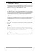
Chapter 3: System Interface Chapter 3 System Interface 3-1 Overview There are several LEDs on the control panel to keep you constantly informed of the overall status of the system as well as the three buttons described below. 3-2 Control Panel Buttons There are three buttons located on the front of the chassis: a UIB button, a reset button and a power on/off button.
SUPERSERVER 1018D-73MTF Manual 3-3 Control Panel LEDs The control panel located on the front of the SC113MTQ chassis has five LEDs. These LEDs provide you with critical information related to different parts of the system. This section explains what each LED indicates when illuminated and any corrective action you may need to take. NIC2 Indicates network activity on LAN2 when flashing. NIC1 Indicates network activity on LAN1 when flashing.
Chapter 3: System Interface Overheat/Fan Fail/UID LED When this LED flashes it indicates a fan failure. When continuously on (not flashing) it indicates an overheat condition, which may be caused by cables obstructing the airflow in the system or the ambient room temperature being too warm. Check the routing of the cables and make sure that all fans are present and operating normally. Also check to make sure that the air shrouds are installed and that the top cover is on.
SUPERSERVER 1018D-73MTF Manual Notes 3-4
Chapter 4: Warning Statements for AC Systems Chapter 4 Standardized Warning Statements for AC Systems 4-1 About Standardized Warning Statements The following statements are industry standard warnings, provided to warn the user of situations which have the potential for bodily injury. Should you have questions or experience difficulty, contact Supermicro's Technical Support department for assistance. Only certified technicians should attempt to install or configure components.
SUPERSERVER 1018D-73MTF User's Manual Warnung WICHTIGE SICHERHEITSHINWEISE Dieses Warnsymbol bedeutet Gefahr. Sie befinden sich in einer Situation, die zu Verletzungen führen kann. Machen Sie sich vor der Arbeit mit Geräten mit den Gefahren elektrischer Schaltungen und den üblichen Verfahren zur Vorbeugung vor Unfällen vertraut.
Warning Statements for AC Systems . ﺗﺤﺬﻳﺮ!ﻫﺬﺍ ﺍﻟﺮﻣﺰ ﻳﻌﻨﻲ ﺧﻄﺮ ﺍﻧﻚ ﻓﻲ ﺣﺎﻟﺔ ﻳﻤﻜﻦ ﺃﻥ ﺗﺘﺴﺒﺐ ﻓﻲ ﺍﺻﺎﺑﺔ ﺟﺴﺪﻳﺔ ﻛﻦ ﻋﻠﻰ ﻋﻠﻢ ﺑﺎﻟﻤﺨﺎﻁﺮ ﺍﻟﻨﺎﺟﻤﺔ ﻋﻦ ﺍﻟﺪﻭﺍﺋﺮ،ﻗﺒﻞ ﺃﻥ ﺗﻌﻤﻞ ﻋﻠﻰ ﺃﻱ ﻣﻌﺪﺍﺕ ﺍﻟﻜﻬﺮﺑﺎﺋﻴﺔ ﻭﻛﻦ ﻋﻠﻰ ﺩﺭﺍﻳﺔ ﺑﺎﻟﻤﻤﺎﺭﺳﺎﺕ ﺍﻟﻮﻗﺎﺋﻴﺔ ﻟﻤﻨﻊ ﻭﻗﻮﻉ ﺃﻱ ﺣﻮﺍﺩﺙ ﺍﺳﺘﺨﺪﻡ ﺭﻗﻢ ﺍﻟﺒﻴﺎﻥ ﺍﻟﻤﻨﺼﻮﺹ ﻓﻲ ﻧﻬﺎﻳﺔ ﻛﻞ ﺗﺤﺬﻳﺮ ﻟﻠﻌﺜﻮﺭ ﺗﺮﺟﻤﺘﻬﺎ 안전을 위한 주의사항 경고! 이 경고 기호는 위험이 있음을 알려 줍니다. 작업자의 신체에 부상을 야기 할 수 있는 상태에 있게 됩니다. 모든 장비에 대한 작업을 수행하기 전에 전기회로와 관련된 위험요소들을 확인하시고 사전에 사고를 방지할 수 있도록 표준 작업절차를 준수해 주시기 바랍니다.
SUPERSERVER 1018D-73MTF User's Manual Installation Instructions Warning! Read the installation instructions before connecting the system to the power source. 設置手順書 システムを電源に接続する前に、設置手順書をお読み下さい。 警告 将此系统连接电源前,请先阅读安装说明。 警告 將系統與電源連接前,請先閱讀安裝說明。 Warnung Vor dem Anschließen des Systems an die Stromquelle die Installationsanweisungen lesen. ¡Advertencia! Lea las instrucciones de instalación antes de conectar el sistema a la red de alimentación.
Chapter 4: Warning Statements for AC Systems Circuit Breaker Warning! This product relies on the building's installation for short-circuit (overcurrent) protection. Ensure that the protective device is rated not greater than: 250 V, 20 A.
SUPERSERVER 1018D-73MTF User's Manual 경고! 이 제품은 전원의 단락(과전류)방지에 대해서 전적으로 건물의 관련 설비에 의존합니다. 보호장치의 정격이 반드시 250V(볼트), 20A(암페어)를 초과하지 않도록 해야 합니다. Waarschuwing Dit product is afhankelijk van de kortsluitbeveiliging (overspanning) van uw electrische installatie. Controleer of het beveiligde aparaat niet groter gedimensioneerd is dan 220V, 20A.
Chapter 4: Warning Statements for AC Systems ¡Advertencia! El sistema debe ser disconnected de todas las fuentes de energía y del cable eléctrico quitado de los módulos de fuente de alimentación antes de tener acceso el interior del chasis para instalar o para quitar componentes de sistema. Attention Le système doit être débranché de toutes les sources de puissance ainsi que de son cordon d'alimentation secteur avant d'accéder à l'intérieur du chassis pour installer ou enlever des composants de systéme.
SUPERSERVER 1018D-73MTF User's Manual Equipment Installation Warning! Only trained and qualified personnel should be allowed to install, replace, or service this equipment. 機器の設置 トレーニングを受け認定された人だけがこの装置の設置、交換、 またはサービスを許可 されています。 警告 只有经过培训且具有资格的人员才能进行此设备的安装、更换和维修。 警告 只有經過受訓且具資格人員才可安裝、更換與維修此設備。 Warnung Das Installieren, Ersetzen oder Bedienen dieser Ausrüstung sollte nur geschultem, qualifiziertem Personal gestattet werden.
Chapter 4: Warning Statements for AC Systems Waarschuwing Deze apparatuur mag alleen worden geïnstalleerd, vervangen of hersteld door geschoold en gekwalificeerd personeel. Restricted Area Warning! This unit is intended for installation in restricted access areas. A restricted access area can be accessed only through the use of a special tool, lock and key, or other means of security. (This warning does not apply to workstations).
SUPERSERVER 1018D-73MTF User's Manual אזור עם גישה מוגבלת !אזהרה הגישה ניתנת בעזרת.יש להתקין את היחידה באזורים שיש בהם הגבלת גישה .(' מנעול וכד,כלי אבטחה בלבד )מפתח . ﺗﻢ ﺗﺨﺼﻴﺺ ﻫﺬﻩ ﺍﻟﻮﺣﺪﺓ ﻟﺘﺮﻛﻴﺒﻬﺎ ﻓﻲ ﻣﻨﺎﻁﻖ ﻣﺤﻈﻮﺭﺓ ،ﻳﻤﻜﻦ ﺍﻟﻮﺻﻮﻝ ﺇﻟﻰ ﻣﻨﻄﻘﺔ ﻣﺤﻈﻮﺭﺓ ﻓﻘﻂ ﻣﻦ ﺧﻼﻝ ﺍﺳﺘﺨﺪﺍﻡ ﺃﺩﺍﺓ ﺧﺎﺻﺔ ﻗﻔﻞ ﻭﻣﻔﺘﺎﺡ ﺃﻭ ﺃﻱ ﻭﺳﻴﻠﺔ ﺃﺧﺮﻯ ﻟﻼﻷﻣﺎﻥ 경고! 이 장치는 접근이 제한된 구역에 설치하도록 되어있습니다. 특수도구, 잠금 장치 및 키, 또는 기타 보안 수단을 통해서만 접근 제한 구역에 들어갈 수 있습니다. Waarschuwing Dit apparaat is bedoeld voor installatie in gebieden met een beperkte toegang.
Chapter 4: Warning Statements for AC Systems Warnung Bei Einsetzen einer falschen Batterie besteht Explosionsgefahr. Ersetzen Sie die Batterie nur durch den gleichen oder vom Hersteller empfohlenen Batterietyp. Entsorgen Sie die benutzten Batterien nach den Anweisungen des Herstellers. Attention Danger d'explosion si la pile n'est pas remplacée correctement. Ne la remplacer que par une pile de type semblable ou équivalent, recommandée par le fabricant.
SUPERSERVER 1018D-73MTF User's Manual Redundant Power Supplies Warning! This unit might have more than one power supply connection. All connections must be removed to de-energize the unit. 冗長電源装置 このユニットは複数の電源装置が接続されている場合があります。 ユニットの電源を切るためには、すべての接続を取り外さなければなりません。 警告 此部件连接的电源可能不止一个,必须将所有电源断开才能停止给该部件供电。 警告 此裝置連接的電源可能不只一個,必須切斷所有電源才能停止對該裝置的供電。 Warnung Dieses Gerät kann mehr als eine Stromzufuhr haben. Um sicherzustellen, dass der Einheit kein trom zugeführt wird, müssen alle Verbindungen entfernt werden.
Chapter 4: Warning Statements for AC Systems .ﻗﺪ ﻳﻜﻮﻥ ﻟﻬﺬﺍ ﺍﻟﺠﻬﺎﺯ ﻋﺪﺓ ﺍﺗﺼﺎﻻﺕ ﺑﻮﺣﺪﺍﺕ ﺍﻣﺪﺍﺩ ﺍﻟﻄﺎﻗﺔ ﻳﺠﺐ ﺇﺯﺍﻟﺔ ﻛﺎﻓﺔ ﺍﻻﺗﺼﺎﻻﺕ ﻟﻌﺰﻝ ﺍﻟﻮﺣﺪﺓ ﻋﻦ ﺍﻟﻜﻬﺮﺑﺎء 경고! 이 장치에는 한 개 이상의 전원 공급 단자가 연결되어 있을 수 있습니다. 이 장치에 전원을 차단하기 위해서는 모든 연결 단자를 제거해야만 합니다. Waarschuwing Deze eenheid kan meer dan één stroomtoevoeraansluiting bevatten. Alle aansluitingen dienen verwijderd te worden om het apparaat stroomloos te maken. Backplane Voltage Warning! Hazardous voltage or energy is present on the backplane when the system is operating.
SUPERSERVER 1018D-73MTF User's Manual מתח בפנל האחורי !אזהרה יש להיזהר במהלך.קיימת סכנת מתח בפנל האחורי בזמן תפעול המערכת .העבודה ﻫﻨﺎﻙ ﺧﻄﺮ ﻣﻦ ﺍﻟﺘﻴﺎﺭ ﺍﻟﻜﻬﺮﺑﺎﺋﻲ ﺃﻭﺍﻟﻄﺎﻗﺔ ﺍﻟﻤﻮﺟﻮﺩﺓ ﻋﻠﻰ ﺍﻟﻠﻮﺣﺔ ﻋﻨﺪﻣﺎ ﻳﻜﻮﻥ ﺍﻟﻨﻈﺎﻡ ﻳﻌﻤﻞ ﻛﻦ ﺣﺬﺭﺍ ﻋﻨﺪ ﺧﺪﻣﺔ ﻫﺬﺍ ﺍﻟﺠﻬﺎﺯ 경고! 시스템이 동작 중일 때 후면판 (Backplane)에는 위험한 전압이나 에너지가 발생 합니다. 서비스 작업 시 주의하십시오. Waarschuwing Een gevaarlijke spanning of energie is aanwezig op de backplane wanneer het systeem in gebruik is. Voorzichtigheid is geboden tijdens het onderhoud.
Chapter 4: Warning Statements for AC Systems Attention L'équipement doit être installé conformément aux normes électriques nationales et locales. תיאום חוקי החשמל הארצי !אזהרה .התקנת הציוד חייבת להיות תואמת לחוקי החשמל המקומיים והארציים ﺗﺮﻛﻴﺐ ﺍﻟﻤﻌﺪﺍﺕ ﺍﻟﻜﻬﺮﺑﺎﺋﻴﺔ ﻳﺠﺐ ﺃﻥ ﻳﻤﺘﺜﻞ ﻟﻠﻘﻮﺍﻧﻴﻦ ﺍﻟﻤﺤﻠﻴﺔ ﻭﺍﻟﻮﻁﻨﻴﺔ ﺍﻟﻤﺘﻌﻠﻘﺔ ﺑﺎﻟﻜﻬﺮﺑﺎء 경고! 현 지역 및 국가의 전기 규정에 따라 장비를 설치해야 합니다. Waarschuwing Bij installatie van de apparatuur moet worden voldaan aan de lokale en nationale elektriciteitsvoorschriften.
SUPERSERVER 1018D-73MTF User's Manual ¡Advertencia! Al deshacerse por completo de este producto debe seguir todas las leyes y reglamentos nacionales. Attention La mise au rebut ou le recyclage de ce produit sont généralement soumis à des lois et/ou directives de respect de l'environnement. Renseignez-vous auprès de l'organisme compétent. סילוק המוצר !אזהרה .
Chapter 4: Warning Statements for AC Systems 警告 當您從機架移除風扇裝置,風扇可能仍在轉動。小心不要將手指、螺絲起子和其他 物品太靠近風扇。 Warnung Die Lüfter drehen sich u. U. noch, wenn die Lüfterbaugruppe aus dem Chassis genommen wird. Halten Sie Finger, Schraubendreher und andere Gegenstände von den Öffnungen des Lüftergehäuses entfernt. ¡Advertencia! Los ventiladores podran dar vuelta cuando usted quite ell montaje del ventilador del chasis.
SUPERSERVER 1018D-73MTF User's Manual Power Cable and AC Adapter Warning! When installing the product, use the provided or designated connection cables, power cables and AC adaptors. Using any other cables and adaptors could cause a malfunction or a fire. Electrical Appliance and Material Safety Law prohibits the use of UL or CSA -certified cables (that have UL/CSA shown on the code) for any other electrical devices than products designated by Supermicro only.
Chapter 4: Warning Statements for AC Systems Attention Lors de l'installation du produit, utilisez les bables de connection fournis ou désigné. L'utilisation d'autres cables et adaptateurs peut provoquer un dysfonctionnement ou un incendie. Appareils électroménagers et de loi sur la sécurité Matériel interdit l'utilisation de UL ou CSA câbles certifiés qui ont UL ou CSA indiqué sur le code pour tous les autres appareils électriques que les produits désignés par Supermicro seulement.
SUPERSERVER 1018D-73MTF User's Manual Notes 4-20
Chapter 5: Advanced Motherboard Setup Chapter 5 Advanced Motherboard Setup This chapter covers the steps required to install processors and heatsinks to the X10SL7-F motherboard, connect the data and power cables and install add-on cards. All motherboard jumpers and connections are described and a layout and quick reference chart are included in this chapter. Remember to close the chassis completely when you have finished working on the motherboard to protect and cool the system sufficiently.
SUPERSERVER 1018D-73MTF User's Manual 5-2 Processor and Heatsink Installation Warning: When handling the processor package, avoid placing direct pressure on the label area of the fan. Notes: Always connect the power cord last and always remove it before adding, re- • moving or changing any hardware components. Make sure that you install the processor into the CPU socket before you install the CPU heatsink.
Chapter 5: Advanced Motherboard Setup 5. Align the CPU key, which is a semicircle cutout, against the socket CPU Key key, which is the notch below the gold color dot on the side of the socket. 6. Align pin 1 of the CPU against pin 1 of the CPU socket. 7. Once both CPU and the socket are aligned, carefully lower the CPU straight down into the socket. (To avoid damaging the CPU or the socket, do not rub the CPU against the surface of the socket or its pins.) 8.
SUPERSERVER 1018D-73MTF User's Manual Installing a CPU Heatsink 1. Remove power from the system and unplug the AC power cord from the power supply. 2. Do not apply any thermal grease to the heatsink or the CPU die; the required amount has already been applied. 3. Place the heatsink on top of the CPU so that the four mounting holes are aligned with those on the (preinstalled) heatsink retention mechanism. 4. Screw in two diagonal screws (i.e. the #1 and the #2 screws) until just snug.
Chapter 5: Advanced Motherboard Setup 5-3 Connecting Cables Now that the processors are installed, the next step is to connect the cables to the motherboard. These include the data (ribbon) cables for the peripherals and control panel and the power cables. Connecting Data Cables The cables used to transfer data from the peripheral devices have been carefully routed in preconfigured systems to prevent them from blocking the flow of cooling air that moves through the system from front to back.
SUPERSERVER 1018D-73MTF User's Manual Figure 5-2. Front Control Panel Header Pins (JF1) 20 19 Ground NMI X X Power LED Vcc HDD LED Vcc NIC1 LED Vcc NIC2 LED Vcc OH/Fan Fail LED Vcc PWR Fail LED Vcc Ground Reset Reset Button Ground PWR Power Button 2 5-4 1 I/O Ports The I/O ports are color coded in conformance with the PC 99 specification. See Figure 5-3 below for the colors and locations of the various I/O ports. Figure 5-3.
Chapter 5: Advanced Motherboard Setup 5-5 Installing Memory Note: Check the Supermicro web site for recommended memory modules. CAUTION Exercise extreme care when installing or removing DIMM modules to prevent any possible damage. Installing DIMMs Insert the desired number of DIMMs into the memory slots, starting with the DIMMA1 slot. 1. Push the release tabs outwards on both ends of the DIMM slot to unlock it. 2. Align the key on the DIMM module with the receptive point on the slot. 3.
SUPERSERVER 1018D-73MTF User's Manual Memory Population Guidelines Please follow the table below when populating the X10SL7-F. DDR3 Unbuffered ECC (UDIMM) Memory DIMM Slots per Channel DIMMs Populated per Channel DIMM Type POR Speeds Ranks per DIMM (any combination) 2 1 Unbuffered DDR3 1333, 1600 Single Rank, Dual Rank 2 2 Unbuffered DDR3 1333, 1600 Single Rank, Dual Rank Notes • • • Be sure to use memory modules of the same type, same speed, same frequency on the same motherboard.
Chapter 5: Advanced Motherboard Setup 5-6 Adding PCI Cards PCI Expansion Slots One riser card is used to support a PCI expansion (add-on) card in the system. The SC113MTQ chassis can accommodate one standard size (full height full length) PCI expansion card. When viewed from the chassis front, the card installs to the left rear of the system. PCI Card Installation Before installing a PCI add-on card, make sure it is supported by the riser card.
SUPERSERVER 1018D-73MTF User's Manual 5-7 Motherboard Details Figure 5-5. SUPER X10SL7-F Layout USB2/3 SW1 LE4 LE5 USB4/5 MAC CODE IPMI CODE JPL1 JPL2 BAR CODE LAN CTRL JPW2 J21 LAN CTRL COM2 IPMI_LAN DIMMB2 DIMMB1 DIMMA2 DIMMA1 SAS CODE JPW1 X10SL7-F USB0 (3.0) Rev. 1.01 CPU BIOS LICENSE USB8/9 CPU1 JSTBY1 LAN1 JTPM1 J3 PCH SLOT5 PCI-E 2.0 X4 (IN X 8) JI2C2 JI2C1 JPME2 JPME1 JBR1 BIOS CPU SLOT6 PCI-E 3.
Chapter 5: Advanced Motherboard Setup Connector Description COM1/COM2 COM1 (Port)/COM2 (Header) Fan1 - Fan4, FanA System/CPU Fan Headers JF1 Front Panel Control Header JL1 Chassis Intrusion Header JLED1 Power LED Indicator Header JPI2C1 Power SMB (System Management Bus) JPW1 24-pin ATX Main Power Connector (Required) JPW2 +12V 8-pin CPU power Connector (Required) JSD1 SATA DOM (Device On_Module) Power Connector JSTBY1 Standby Power Header JTPM1 Trusted Platform Module/Port 80 Connect
SUPERSERVER 1018D-73MTF User's Manual 5-8 Connector Definitions ATX Power 24-pin Connector Pin Definitions (JPW1) Power Connectors The 24 - pin main power connector (JPW1) is used to provide power to the motherboard. The 8-pin CPU PWR connector (JPW2) is also required for the processor. These power connectors meet the SSI EPS 12V specification. See the tables on the right for pin definitions. Pin# Definition Pin # Definition 13 +3.3V 1 +3.3V 14 -12V 2 +3.
Chapter 5: Advanced Motherboard Setup NIC1/NIC2 (LAN1/LAN2) GLAN1/2 LED Pin Definitions (JF1) The NIC (Network Interface Controller) LED connection for LAN port 1 is located Pin# on pins 11 and 12 of JF1, and the LED connection for LAN Port 2 is on pins 9 and 10. Attach NIC LED cables to NIC1 LED and NIC2 LED to display network Definition 9 Vcc 10 NIC 2 Link/Acitivty LED 11 Vcc 12 NIC 1 Link/Acitivty LED activities for LAN 1 and LAN2. Refer to the table on the right for pin definitions.
SUPERSERVER 1018D-73MTF User's Manual Power Button The Power Button connection is located on pins 1 and 2 of JF1. Momentarily Power Button Pin Definitions (JF1) contacting both pins will power on/off the system. This button can also be config- Pin# Definition ured to function as a suspend button (see 1 Signal BIOS Setup). To turn off the power in the 2 Ground suspend mode, press the button for at least 4 seconds. Refer to the table on the right for pin definitions. Back Panel USB (2.
Chapter 5: Advanced Motherboard Setup Fan Headers The X10SL7-F has five fan headers (Fan1 - Fan4 and FanA). These are all 4-pin fan Fan Header Pin Definitions headers, however pins 1-3 are backward compatible with traditional 3-pin fans. Fan Pin# Definition speed is controlled via IPMI based on the system temperature. Refer to the table on 1 Ground (Black) 2 2.5A/+12V (Red) the right for pin definitions. 3 Tachometer 4 PWM_Control Note: Please use all 3-pin fans or all 4-pin fans.
SUPERSERVER 1018D-73MTF User's Manual DOM PWR Connector DOM PWR Pin Definitions The Disk-On-Module (DOM) power connector (JSD1) provides 5V power to a solid state DOM storage device connected to one of the SATA ports. See the table on the right for pin definitions. Pin# Definition 1 5V 2 Ground 3 Ground Standby Power Pin Definitions Standby Power Pin# The Standby Power header is located at JSTBY1 on the motherboard. See the table at right for pin definitions.
Chapter 5: Advanced Motherboard Setup LAN Ports Pin Definition Pin# Definition Ethernet Ports 1 P2V5SB 10 SGND 2 TD0+ 11 Act LED 3 TD0- 12 P3V3SB 4 TD1+ 13 Link 100 LED (Yellow, +3V3SB) LAN port is included located above the USB ports on the backplane to provide 5 TD1- 14 Link 1000 LED (Yellow, +3V3SB) KVM support for IPMI 2.0. All these 6 TD2+ 15 Ground ports accept RJ45 type cables.
SUPERSERVER 1018D-73MTF User's Manual Onboard Power LED (JLED1) Onboard PWR LED Pin Definitions An onboard Power LED header is located at JLED1. This Power LED header connects to JF1 to indicate the status of system power. See the table on the right for pin definitions. Pin# Definition 1 Vcc 2 No Connection 3 Connection to PWR LED in JF1 Internal Buzzer (SP1) Internal Buzzer Pin Definition The Internal Buzzer (SPKR1) can be used to provide audible indications for various beep codes.
Chapter 5: Advanced Motherboard Setup 5-9 Jumper Settings Explanation of Jumpers To modify the operation of the motherboard, jumpers can be used to choose between optional settings. Jumpers cre- 3 2 1 3 2 1 Connector Pins ate shorts between two pins to change the function of the connector. Pin 1 is identified with a square solder pad on the Jumper printed circuit board. See the diagram at right for an example of jumping pins 1 and Setting 2.
SUPERSERVER 1018D-73MTF User's Manual PCI-E Slot SMB Enable (I2C1/I2C2) Use Jumpers I2C1/I2C2 to enable PCI-E PCI-E Slot_SMB Enable Jumper Settings SMB (System Management Bus) support Jumper Setting to improve system management for the PCI-E slots. See the table on the right for Pins 1-2 Enabled Pins 2-3 Disabled Definition jumper settings. LAN Port Enable/Disable Use JPL1/JPL2 to enable or disable LAN Ports 1 and 2 on the motherboard. See the table on the right for jumper settings.
Chapter 5: Advanced Motherboard Setup ME Recovery Set Jumper JPME1 to select ME Firmware Recovery mode, which will limit ME Recovery Jumper Settings system resource for essential function use only without putting restrictions on power use. In the single operation mode, online upgrade will be available via Re- Jumper Setting Definition Pins 1-2 Normal (Default) Pins 2-3 ME Recovery covery mode. See the table on the right for jumper settings.
SUPERSERVER 1018D-73MTF User's Manual 5-10 Onboard Indicators LAN1/LAN2 LEDs LAN LED Connection Speed Indication The Ethernet ports (located beside the VGA port) have two LEDs. On each Giga- LED State Definition bit LAN port, the yellow LED indicates Off No connection or 10 Mb/s activity when blinking while the other LED Green 100 Mbps may be green, amber or off to indicate the speed of the connection.
Chapter 5: Advanced Motherboard Setup Power Status LED (LE6) Power Status LED Color Definition A Power Status LED is located at LE6 on the motherboard. When the LED indica- Green System Power On (Power Normal) tor turns to color red, power supply has a Yellow Standby Power Active (System Off) problem. See the table at right for more Red System Power has a problem (Power Failure) information.
SUPERSERVER 1018D-73MTF User's Manual 5-12 Installing Software The Supermicro ftp site contains drivers and utilities for your system at ftp://ftp. supermicro.com. Some of these must be installed, such as the chipset driver. After accessing the ftp site, go into the CDR_Images directory and locate the ISO file for your motherboard. Download this file to create a CD/DVD of the drivers and utilities it contains. (You may also use a utility to extract the ISO file if preferred.
Chapter 5: Advanced Motherboard Setup SuperDoctor III The SuperDoctor® III program is a web-based management tool that supports remote management capability. It includes Remote and Local Management tools. The local management is called SD III Client. The SuperDoctor III program allows you to monitor the environment and operations of your system. SuperDoctor III displays crucial system information such as CPU temperature, system voltages and fan status.
SUPERSERVER 1018D-73MTF User's Manual Figure 5-8. SuperDoctor III Interface Display Screen (Remote Control) Note: The SuperDoctor III program and User’s Manual can be downloaded from the Supermicro web site at http://www.supermicro.com/products/accessories/software/SuperDoctorIII.cfm. For Linux, we recommend that you use the SuperDoctor II application instead. 5-13 Onboard Battery Please handle used batteries carefully.
Chapter 6: Advanced Chassis Setup Chapter 6 Advanced Chassis Setup This chapter covers the steps required to install components and perform maintenance on the SC113MTQ-330CB chassis. For component installation, follow the steps in the order given to eliminate the most common problems encountered. If some steps are unnecessary, skip ahead to the next step. Tools Required: The only tool you will need to install components and perform maintenance is a Philips screwdriver.
SUPERSERVER 1018D-73MTF User's Manual Figure 6-1. Chassis: Front and Rear Views Control Panel SATA Drive Bays (8) Power Supply Dedicated IPMI LAN Port COM Port 6-2 VGA Port PCI Slot USB Ports LAN Ports Control Panel The control panel (located on the front of the chassis) must be connected to the JF1 connector on the motherboard to provide you with system status indications. A ribbon cable has bundled these wires together to simplify the connection.
Chapter 6: Advanced Chassis Setup Adding a System Fan 1. Turn off the power to the system and unplug the power cord. 2. Remove the chassis cover then remove the dummy fan from the fan tray. 3. Place the new fan into the vacant space in the housing while making sure the arrows on the top of the fan (indicating air direction) point in the same direction as the arrows on the other fans. 4. Connect the fan wires to the fan header on the motherboard. 5.
SUPERSERVER 1018D-73MTF User's Manual Figure 6-2: Replacing a System Fan (shown with optional fan housings) 6-4 Drive Bay Installation/Removal Accessing the Drive Bays Hard Drives: Because of their hotswap capability, you do not need to access the inside of the chassis or power down the system to install or replace hard drives. Proceed to the next section for instructions.
Chapter 6: Advanced Chassis Setup 2. Align the drive in the carrier so that the screw holes of both line up. Note that there are holes in the carrier marked “SATA” to aid in correct installation. 3. Secure the drive to the carrier with four screws as illustrated below. 4. Insert the drive carrier into its bay, keeping the carrier oriented so that the hard drive is on the top of the carrier and the release button is on the right side.
SUPERSERVER 1018D-73MTF User's Manual Figure 6-4. Removing a Hard Drive 12 1 DVD Drive Installation The SC113MTQ chassis may have a DVD-ROM installed (optional). Installing or Replacing a DVD-ROM Drive (Figure 6-5) 1. Power down the system and if necessary, remove the server from the rack and the front bezel from the chassis. 2. Remove the chassis cover. 3. Unplug the drives power and data cables from the motherboard and/or backplane. 4.
Chapter 6: Advanced Chassis Setup Figure 6-5.
SUPERSERVER 1018D-73MTF User's Manual 6-5 Power Supply The SuperServer 1018D-73MTF has a single 330 watt power supply, which is autoswitching capable. This enables it to automatically sense and operate with a 100V to 240V input voltage. Power Supply Failure If the power supply unit fails, the system will shut down and you will need to replace the unit. Replacement units can be ordered directly from Supermicro (see contact information in the Preface).
Chapter 6: Advanced Chassis Setup Figure 6-6.
SUPERSERVER 1018D-73MTF User's Manual Notes 6-10
Chapter 7: BIOS Chapter 7 BIOS 7-1 Introduction This chapter describes the AMI BIOS Setup Utility for the X10SL7-F. The ROM BIOS is stored in a Flash EEPROM and can be easily updated. This chapter describes the basic navigation of the AMI BIOS Setup Utility setup screens. Note: For AMI BIOS Recovery, please refer to the UEFI BIOS Recovery Instructions in Appendix C. Starting BIOS Setup Utility To enter the AMI BIOS Setup Utility screens, press the key while the system is booting up.
SUPERSERVER 1018D-73MTF User's Manual How to Start the Setup Utility Normally, the only visible Power-On Self-Test (POST) routine is the memory test. As the memory is being tested, press the key to enter the main menu of the AMI BIOS Setup Utility. From the main menu, you can access the other setup screens. An AMI BIOS identification string is displayed at the left bottom corner of the screen, below the copyright message.
Chapter 7: BIOS The following Main menu items will display: System Time/System Date Use this option to change the system date and time. Highlight System Date or System Time using the arrow keys. Enter new values through the keyboard. Press the key or the arrow keys to move between fields. The date must be entered in Day MM/DD/YY format. The time is entered in HH:MM:SS format. Note: The time is in the 24-hour format. For example, 5:30 P.M. appears as 17:30:00.
SUPERSERVER 1018D-73MTF User's Manual 7-3 Advanced Setup Configurations Use the arrow keys to select Boot Setup and press to access the submenu items: Warning: Take Caution when changing the Advanced settings. An incorrect value, a very high DRAM frequency, or an incorrect DRAM timing setting may make the system unstable. When this occurs, revert to the setting to its manufacture default setting.
Chapter 7: BIOS Wait For 'F1' If Error This feature forces the system to wait until the 'F1' key is pressed if an error occurs. The options are Disabled and Enabled. Interrupt 19 Capture Interrupt 19 is the software interrupt that handles the boot disk function. When this item is set to Enabled, the ROM BIOS of the host adaptors will "capture" Interrupt 19 at bootup and allow the drives that are attached to these host adaptors to function as bootable disks.
SUPERSERVER 1018D-73MTF User's Manual CPU Configuration The following CPU information will be displayed: • Type of CPU • CPU Signature • Microcode Patch • Max (Maximum) CPU Speed • Min (Minimum) CPU Speed • CPU Speed • Processor Cores • Intel HT(Hyper-Threading) Technology • Intel VT-x (Virtualization) Technology • Intel SMX (Trusted Execution) Technology • 64-bit • EIST Technology • CPU C3 State • CPU C6 State • CPU C7 State • L1 Data Cache • L1 Code Cache • L2 Cache
Chapter 7: BIOS Hyper-threading Select Enabled to support Intel Hyper-threading Technology to enhance CPU performance. The options are Enabled and Disabled. Active Processor Cores This feature determines how many CPU cores will be activated for each CPU. When all is selected, all cores in the CPU will be activated. (Please refer to Intel's web site for more information.) The options are All, 1, 2, and 3.
SUPERSERVER 1018D-73MTF User's Manual CPU AES Select Enable to enable Intel CPU Advanced Encryption Standard (AES) Instructions for CPU to enhance data integrity. The options are Enabled and Disabled. EIST EIST (Enhanced Intel SpeedStep Technology) allows the system to automatically adjust processor voltage and core frequency in an effort to reduce power consumption and heat dissipation. Please refer to Intel’s web site for detailed information. The options are Disabled and Enabled.
Chapter 7: BIOS 1-Core Ratio Limit (Available when "Turbo Mode" is set to Enabled) This increases (multiplies) 1 clock speed in the CPU core in relation to the bus speed when one CPU core is active. Press "+" or "-" on your keyboard to change the value. Enter 0 to use the manufacture default setting. 2-Core Ratio Limit (Available when "Turbo Mode" is set to Enabled) This increases (multiplies) 2 clock speeds in the CPU core in relation to the bus speed when two CPU cores are active.
SUPERSERVER 1018D-73MTF User's Manual CPU C3 Report (Available when "CPU C-States" is set to Enabled) Select Enabled to allow the BIOS to report the CPU C3 State (ACPI C2) to the operating system. During the CPU C3 State, the CPU clock generator is turned off. The options are Enabled and Disabled. CPU C6 Report (Available when "CPU C-States" is set to Enabled) Select Enabled to allow the BIOS to report the CPU C6 State (ACPI C3) to the operating system.
Chapter 7: BIOS Package C-State limit Select Auto for the AMI BIOS to automatically set the limit on the C-State package register. The options are C0/C1, C2, C3, C6, C7 and Auto. Chipset Configuration Warning! Setting the wrong values in the following sections may cause the system to malfunction.
SUPERSERVER 1018D-73MTF User's Manual Primary PCIE (PCI-Express Device) This feature allows the user to specify which graphics card to be used as the primary graphics card. The options are PCIE1, PCIE2, PCIE3, PCIE4, PCIE5 , PCIE6, PCIE7 and Auto. PCI-E Configuration This item displays the information of the (graphics) device installed on a PCI-E slot. Riser Card on CPU Slot 6 PEG0 Gen X/PEG1 Gen X/PEG2 Gen X This feature allows the user to select PCI-E support for the device installed on SLOT6.
Chapter 7: BIOS Memory Configuration This item displays the information on the memory modules installed on the motherboard. • Memory RC Version • Memory Frequency • Total Memory • Memory Voltage • DIMMA1 • DIMMA2 • DIMMB1 • DIMMB2 • CAS Latency (tCL) • Minimum Delay Time • CAS to RAS (tRODmin) • Row Precharge (tRPmin) • Active to Precharege (tRASmin) Memory Frequency Limiter This feature sets the limit of memory frequency for DIMM modules installed on the the motherboard.
SUPERSERVER 1018D-73MTF User's Manual Memory Scrambler This feature enables or disables memory scrambler support for memory error correction. The settings are Enabled and Disabled. PCH-IO Configuration This item displays the information for PCH-IO Chip. • Intel PCH Rev ID • USB Configuration • USB Devices EHCI1 Select Enabled to enable EHCI (Enhanced Host Controller Interface) Controller 1 for USB 2.0 support. One EHCI controller must always be enabled. The settings are Enabled and Disabled.
Chapter 7: BIOS EHCI Hand-Off This item is for Operating Systems that do not support Enhanced Host Controller Interface (EHCI) hand-off. When this item is enabled, EHCI ownership change will be claimed by the EHCI driver. The settings are Enabled and Disabled. XHCI Mode This feature handles the operation mode for the XHCI (Extensible Host Controller Interface) controller. The settings are Smart Auto, Auto, Enabled, Disabled and Manual.
SUPERSERVER 1018D-73MTF User's Manual Port 0 ~ Port 1 SATA Device Type This feature configures the selected SATA port to support either a solid state drive or hard disk drive. The options are Hard Disk Drive and Solid Sate Drive. Port 0 ~ Port 5 Spin Up Device On an edge detect from 0 to 1, set this item to allow the PCH to start a COMRESET initialization sequence to the device. The options are Enabled and Disabled.
Chapter 7: BIOS PCIe/PCI/PnP Configuration This feature allows the user to set the PCI/PnP configurations for the following items: Above 4G Decoding Select Enabled for 64-bit devices to be decoded above the 4GB address space If 64bit PCI decoding is supported by the system. The options are Disabled and Enabled.
SUPERSERVER 1018D-73MTF User's Manual Onboard LAN1/LAN2 Option ROM Select iSCSI to use the iSCSI Option ROM to boot the computer using an iSCSI device installed in a LAN port specified. Select PXE (Preboot Execution Environment) to boot the computer using a PXE device installed in a LAN port specified. Select Disabled to prevent system boot using a device installed in a LAN port to boot the system. The options for Onboard LAN1 Option ROM are Disabled, PXE and iSCSI.
Chapter 7: BIOS Intel Server Platform Services Configuration The following status information for this motherboard are displayed: • ME (Management Engine) BIOS Interface Version • SPS Version • ME FW (Firmware) Status Value • ME FW State • ME FW Operation State • ME FW Error Code • ME NM FW Status Value • BIOS Booting Mode • Cores Disabled • ME FW SKU Information • End-of-POST Status Trusted Computing Configuration (Available when a TPM Device is Detected and TPM Jumper is Enabl
SUPERSERVER 1018D-73MTF User's Manual Pending Operation Use this item to schedule a TPM-related operation to be performed by a security device for TPM support. The options are None, Enable Take Ownership, Disable Take Ownership, and TPM Clear. Note: The computer will reboot to carry out a pending TPM operation and change TPM state for a TPM device.
Chapter 7: BIOS Serial Port Console Redirection COM1/COM2 Use this feature to enable console redirection for COM1 and COM2 ports. The options are Enabled and Disabled. The default setting is Disabled. Console Redirection Settings This feature allows the user to specify how the host computer will exchange data with the client computer, which is the remote computer used by the user. Terminal Type This feature allows the user to select the target terminal emulation type for Console Redirection.
SUPERSERVER 1018D-73MTF User's Manual Flow Control This feature allows the user to set the flow control for Console Redirection to prevent data loss caused by buffer overflow. Send a "Stop" signal to stop sending data when the receiving buffer is full. Send a "Start" signal to start sending data when the receiving buffer is empty. The options are None and Hardware RTS/CTS. VT-UTF8 Combo Key Support Select Enabled to enable VT-UTF8 Combination Key support for ANSI/VT100 terminals.
Chapter 7: BIOS Console Redirection Settings (for EMS) This feature allows the user to specify how the host computer will exchange data with the client computer, which is the remote computer used by the user. Out-of-Band Management Port The feature selects a serial port used by the Microsoft Windows Emergency Management Services (EMS) to communicate with a remote server. The options are COM1 and COM2.
SUPERSERVER 1018D-73MTF User's Manual H/W (Hardware) Monitor PC Health Status Fan Speed Control Mode This feature allows the user to decide how the system controls the speeds of the onboard fans. The CPU temperature and the fan speed are correlative. When the CPU on-die temperature increases, the fan speed will also increase for effective system cooling. Select "Full Speed" to allow the onboard fans to run at full speed (of 100% Pulse Width Modulation Duty Cycle) for maximum cooling.
Chapter 7: BIOS 7-4 Event Logs Change SMBIOS Event Log Settings Enabling/Disabling Options SMBIOS Event Log Change this item to enable or disable all features of the SMBIOS Event Logging during system boot. The options are Enabled and Disabled. Erasing Settings Erase Event Log If No is selected, data stored in the event log will not be erased. Select Yes, Next Reset, data in the event log will be erased upon next system reboot.
SUPERSERVER 1018D-73MTF User's Manual MECI The Multiple Event Count Increment (MECI) counter counts the number of occurences a duplicate event must happen before the MECI counter is incremented. This is a numeric value. The default value is 1. METW The Multiple Event Time Window (METW) defines number of minutes must pass between duplicate log events before MECI is incremented. This is in minutes, from 0 to 99. The default value is 60.
Chapter 7: BIOS 7-5 IPMI The following IPMI information will be displayed: • IPMI Firmware Revision • IPMI Status System Event Log This feature is used to change the System Event Log (SEL) configuration. SEL Components - Change this item to enable or disable all features of System Event Logging. The options are Enabled and Disabled. When this feature is set to Enabled, the following can be configured: Erase SEL - This option erases all logged SEL events.
SUPERSERVER 1018D-73MTF User's Manual BMC Network Configuration LAN Channel 1: This feature allows the user to configure the settings for LAN1 Port. Update IPMI LAN Configuration This feature allows the BIOS to implement any IP/MAC address changes at the next system boot. If the option is set to Yes, any changes made to the settings below will take effect when the system is rebooted. The options are No and Yes. IPMI LAN Selection This feature displays the IPMI LAN Selection setting.
Chapter 7: BIOS 7-6 Boot Settings Use this feature to configure Boot Settings: Set Boot Priority This option prioritizes the order of bootable devices that the system to boot from. Press [ENTER] on each entry from top to bottom to select devices.
SUPERSERVER 1018D-73MTF User's Manual Delete Boot Option Use this feature to remove a pre-defined boot device from which the system will boot during startup. The settings are [any pre-defined boot device] Delete Driver Option This feature allows the user to delete a previously defined boot device from which the systems boots during startup.
Chapter 7: BIOS 7-7 Security Settings This menu allows the user to configure the following security settings for the system. • If the Administrator password is defined ONLY - this controls access to the BIOS setup ONLY. • If the User's password is defined ONLY - this password will need to be entered upon each system boot, and will also have Administrator rights in the setup. • Passwords must be at least 3 and up to 20 characters long.
SUPERSERVER 1018D-73MTF User's Manual 7-8 Save & Exit Select the Exit tab from the BIOS Setup Utility screen to enter the Exit BIOS Setup screen. Discard Changes and Exit Select this option to quit the BIOS Setup without making any permanent changes to the system configuration, and reboot the computer. Select Discard Changes and Exit from the Exit menu and press .
Chapter 7: BIOS Restore Optimized Defaults To set this feature, select Restore Defaults from the Exit menu and press . These are factory settings designed for maximum system stability, but not for maximum performance. Save As User Defaults To set this feature, select Save as User Defaults from the Exit menu and press . This enables the user to save any changes to the BIOS setup for future use.
SUPERSERVER 1018D-73MTF User's Manual Notes 7-34
Appendix A: POST Error Beep Codes Appendix A POST Error Beep Codes During the POST (Power-On Self-Test) routines, which are performed each time the system is powered on, errors may occur. Non-fatal errors are those which, in most cases, allow the system to continue with bootup. The error messages normally appear on the screen. Fatal errors will not allow the system to continue to bootup. If a fatal error occurs, you should consult with your system manufacturer for possible repairs.
SUPERSERVER 1018D-73MTF User's Manual Notes A-2
Appendix B: System Specifications Appendix B System Specifications Processors Single Intel® Xeon® E3-1200 v3 or a 4th Generation Core i3/ i5/ i7 processor in an LGA1150 socket Note: Please refer to our web site for a complete listing of supported processors. Chipset Intel C222 BIOS 128 Mb SPI AMI® Flash Memory Capacity Four DIMM sockets that can support 32 GB of Unbuffered ECC DDR31600/1333 memory See the memory section in Chapter 5 for details.
SUPERSERVER 1018D-73MTF User's Manual Chassis SC113MTQ Form Factor: 1U rackmount Dimensions: (WxHxD) 17.2 x 1.7 x 19.85 in. (437 x 43 x 504 mm) Weight Gross Weight: 30 lbs. (13.6 kg.) System Cooling Four 4-cm counter-rotating PWM fans System Input Requirements AC Input Voltage: 100-240V AC auto-range Rated Input Current: 6.3A (115V) to 3.24A (230V) Rated Input Frequency: 50 to 60 Hz Power Supply Rated Output Power: 330W (Part# PWS-333-1H) Rated Output Voltages: +3.
Appendix B: System Specifications This Perchlorate warning applies only to products containing CR (Manganese Dioxide) Lithium coin cells. “Perchlorate Material-special handling may apply. See www.dtsc.ca.gov/hazardouswaste/perchlorate”California Best Management Practices Regulations for Perchlorate Materials: This Perchlorate warning applies only to products containing CR (Manganese Dioxide) Lithium coin cells. “Perchlorate Material-special handling may apply. See www.dtsc.ca.
SUPERSERVER 1018D-73MTF User's Manual Notes B-4