SUPER ® SuperWorkstation 7045A-C3 SuperWorkstation 7045A-CT USER’S MANUAL 1.
The information in this User’s Manual has been carefully reviewed and is believed to be accurate. The vendor assumes no responsibility for any inaccuracies that may be contained in this document, makes no commitment to update or to keep current the information in this manual, or to notify any person or organization of the updates. Please Note: For the most up-to-date version of this manual, please see our web site at www.supermicro.com. Super Micro Computer, Inc.
Preface Preface About This Manual This manual is written for professional system integrators and PC technicians. It provides information for the installation and use of the SuperWorkstation 7045AC3/7045A-CT. Installation and maintenance should be performed by experienced technicians only.
SuperWorkstation 7045A-C3/7045A-CT User's Manual Chapter 4: System Safety You should thoroughly familiarize yourself with this chapter for a general overview of safety precautions that should be followed when installing and servicing the SuperWorkstation 7045A-C3/7045A-CT. Chapter 5: Advanced Serverboard Setup Chapter 5 provides detailed information on the X7DCA-3/X7DCA-i serverboard, including the locations and functions of connections, headers and jumpers.
Preface Notes v
SuperWorkstation 7045A-C3/7045A-CT User's Manual Table of Contents Chapter 1 Introduction 1-1 Overview ......................................................................................................... 1-1 1-2 Serverboard Features ..................................................................................... 1-2 Processors ...................................................................................................... 1-2 Memory ......................................................
Table of Contents Installing the Rack Rails ................................................................................. 2-6 Installing the Server into the Rack .................................................................. 2-7 2-5 Checking the Serverboard Setup .................................................................... 2-8 2-6 Checking the Drive Bay Setup ........................................................................ 2-9 Chapter 3 System Interface 3-1 Overview ...........
SuperWorkstation 7045A-C3/7045A-CT User's Manual X7DCA-3/X7DCA-i Quick Reference ............................................................ 5-13 5-9 Connector Definitions ................................................................................... 5-14 5-10 Jumper Settings ............................................................................................ 5-21 5-11 Onboard Indicators........................................................................................
Chapter 1: Introduction Chapter 1 Introduction 1-1 Overview The 7045A-C3/7045A-CT is a high-end workstation comprised of two main subsystems: the SC743TQ-865-SQ tower/4U server chassis and the X7DCA-3/X7DCA-i dual Intel Xeon processor serverboard. Please refer to our web site for information on operating systems that have been certified for use with the SuperWorkstation 7045A-C3/7045A-CT (www.supermicro.com).
SuperWorkstation 7045A-C3/7045A-CT User's Manual 1-2 Serverboard Features At the heart of the SuperWorkstation 7045A-C3/7045A-CT lies the X7DCA3/X7DCA-i, a dual processor serverboard based on the Intel 5100 chipset and designed to provide maximum performance. Below are the main features of the X7DCA-3/X7DCA-i. (See Figure 1-1 for a block diagram of the chipset).
Chapter 1: Introduction Onboard Controllers/Ports One floppy drive connector and one onboard ATA/100 connector are provided to support IDE hard drives or ATAPI devices. The color-coded rear I/O ports include two COM ports, one parallel port, four USB 2.0 ports, PS/2 mouse and keyboard ports, two gigabit Ethernet ports and HDA (High Definition Audio) ports.
SuperWorkstation 7045A-C3/7045A-CT User's Manual I/O Backplane The SC743TQ-865-SQ is an ATX form factor chassis that can be used as a tower or mounted in a 4U rackmount configuration. The I/O backplane provides seven expansion slots, two COM ports, a parallel port, four USB 2.0 ports, PS/2 mouse and keyboard ports, two Gigabit Ethernet port(s) and 7.1 HDA ports.
Chapter 1: Introduction Figure 1-1. Intel 5100 Chipset: System Block Diagram Note: This is a general block diagram. Please see Chapter 5 for details.
SuperWorkstation 7045A-C3/7045A-CT User's Manual 1-4 Contacting Supermicro Headquarters Address: Super Micro Computer, Inc. 980 Rock Ave. San Jose, CA 95131 U.S.A. Tel: +1 (408) 503-8000 Fax: +1 (408) 503-8008 Email: marketing@supermicro.com (General Information) support@supermicro.com (Technical Support) Web Site: www.supermicro.com Europe Address: Super Micro Computer B.V.
Chapter 2: Server Installation Chapter 2 Server Installation 2-1 Overview This chapter provides a quick setup checklist to get your SuperWorkstation 7045AC3/7045A-CT up and running. Following these steps in the order given should enable you to have the system operational within a minimum amount of time. This quick setup assumes that your system has come to you with the processors and memory preinstalled. If your system is not already fully integrated with a serverboard, processors, system memory etc.
SuperWorkstation 7045A-C3/7045A-CT User's Manual Choosing a Setup Location • Leave enough clearance in front of the rack to enable you to open the front door completely (~25 inches) and approximately 30 inches of clearance in the back of the rack to allow for sufficient airflow and ease in servicing. • • This product is for installation only in a Restricted Access Location (dedicated equipment rooms, service closets and the like).
Chapter 2: Server Installation • Allow the hot plug SAS/SATA drives and power supply modules to cool before touching them. • Always keep the rack's front door and all panels and components on the servers closed when not servicing to maintain proper cooling. Rack Mounting Considerations Ambient Operating Temperature If installed in a closed or multi-unit rack assembly, the ambient operating temperature of the rack environment may be greater than the ambient temperature of the room.
SuperWorkstation 7045A-C3/7045A-CT User's Manual 2-4 Installing the System into a Rack This section provides information on installing the system into a rack unit. Rack installation requires the use of the optional rackmount kit. If the system has already been mounted into a rack or if you are using it as a tower, you can skip ahead to Sections 2-5 and 2-6. There are a variety of rack units on the market, which may mean the assembly procedure will differ slightly.
Chapter 2: Server Installation Installing the Chassis Rails You will need to remove the top cover and the feet to add rack rails to the chassis. First, remove the top and right covers (top and left covers when standing as a tower chassis) by first removing the screws that secure them to the chassis. Depress the button on the top (side if tower) of the chassis to release the cover and then pull the cover off. Then unscrew the four feet and remove them from the chassis (see Figure 2-2).
SuperWorkstation 7045A-C3/7045A-CT User's Manual Figure 2-3. Installing the Rails to the Chassis Installing the Rack Rails Determine where you want to place the SuperWorkstation 7045A-C3/7045A-CT in the rack. (See Rack and Server Precautions in Section 2-3.) Position the fixed rack rail/sliding rail guide assemblies at the desired location in the rack, keeping the sliding rail guide facing the inside of the rack. Screw the assembly securely to the rack using the brackets provided.
Chapter 2: Server Installation Installing the Server into the Rack You should now have rails attached to both the chassis and the rack unit. The next step is to install the server into the rack. You should have two brackets in the rack mount kit. Install these first keeping in mind that they are left/right specific (marked with "L" and "R"). Then, line up the rear of the chassis rails with the front of the rack rails.
SuperWorkstation 7045A-C3/7045A-CT User's Manual 2-5 Checking the Serverboard Setup After setting up the the system, you will need to open the unit to make sure the serverboard is properly installed and all the connections have been made. Accessing the Inside of the System 1. If rack mounted, first release the retention screws that secure the unit to the rack. Then grasp the two handles on either side and pull the unit straight out until it locks (you will hear a "click"). 2.
Chapter 2: Server Installation Figure 2-5. Accessing the Inside of the System (Rack Configuration shown) 2-6 Checking the Drive Bay Setup Next, you should check to make sure the peripheral drives and the SAS/SATA drives and backplane have been properly installed and all connections have been made. Checking the Drives 1. All drives can be accessed from the front of the server. For servicing the CDROM, IDE hard drives and floppy drives, you will need to remove the top/left chassis cover.
SuperWorkstation 7045A-C3/7045A-CT User's Manual 4. Depending upon your system's configuration, your system may have one or more drives already installed. If you need to install SAS/SATA drives, please refer to Chapter 6. Checking the Airflow 1. Airflow is provided by four hot-swap 8-cm chassis fans working in conjunction with an air shroud. One 9-cm exhaust fan is also mounted at the rear of the chassis. The system component layout was carefully designed to promote sufficient airflow through the chassis. 2.
Chapter 3: System Interface Chapter 3 System Interface 3-1 Overview The control panel on the 7045A-C3/7045A-CT has several LEDs and two buttons. There are also two LEDs on each SAS/SATA drive carrier. These LEDs keep you constantly informed of the overall status of the system and the activity and health of specific components. 3-2 Control Panel Buttons There are two push-buttons located on the front of the chassis: a power on/off button and a reset button.
SuperWorkstation 7045A-C3/7045A-CT User's Manual 3-3 Control Panel LEDs The control panel located on the front of the SC743TQ-865-SQ chassis has six LEDs that provide you with critical information related to different parts of the system. This section explains what each LED indicates when illuminated and any corrective action you may need to take. Power Indicates power is being supplied to the system's power supply. This LED should normally be on when the system is operating.
Chapter 3: System Interface airflow in the system or the ambient room temperature being too warm. Check the routing of the cables and make sure all fans are present and operating normally. You should also check to make sure that the chassis covers are installed. Finally, verify that the heatsinks are installed properly (see Chapter 5). This LED will remain flashing or on as long as the indicated condition exists. Power Fail Indicates a power supply fan has failed.
SuperWorkstation 7045A-C3/7045A-CT User's Manual Notes 3-4
Chapter 4: System Safety Chapter 4 System Safety 4-1 Electrical Safety Precautions ! Basic electrical safety precautions should be followed to protect yourself from harm and the SuperWorkstation 7045A-C3/7045A-CT from damage: • • • • • • • Be aware of the locations of the power on/off switch on the chassis as well as the room's emergency power-off switch, disconnection switch or electrical outlet. If an electrical accident occurs, you can then quickly remove power from the system.
SuperWorkstation 7045A-C3/7045A-CT User's Manual • Serverboard Battery: CAUTION - There is a danger of explosion if the onboard battery is installed upside down, which will reverse its polarities (see Figure 4-1). This battery must be replaced only with the same or an equivalent type recommended by the manufacturer. Dispose of used batteries according to the manufacturer's instructions. • CD-ROM Laser: CAUTION - this server may have come equipped with a CDROM drive.
Chapter 4: System Safety • After accessing the inside of the system, close the system back up and secure it to the rack unit with the retention screws after ensuring that all connections have been made. 4-3 ESD Precautions ! Electrostatic discharge (ESD) is generated by two objects with different electrical charges coming into contact with each other. An electrical discharge is created to neutralize this difference, which can damage electronic components and printed circuit boards.
SuperWorkstation 7045A-C3/7045A-CT User's Manual 4-4 Operating Precautions ! Care must be taken to assure that the chassis cover is in place when the 7045AC3/7045A-CT is operating to assure proper cooling. Out of warranty damage to the 7045A-C3/7045A-CT system can occur if this practice is not strictly followed. Figure 4-1.
Chapter 5: Advanced Serverboard Setup Chapter 5 Advanced Serverboard Setup This chapter covers the steps required to install the X7DCA-3/X7DCA-i serverboard into the chassis, connect the data and power cables and install add-on cards. All serverboard jumpers and connections are also described. A layout and quick reference chart are included in this chapter for your reference. Remember to completely close the chassis when you have finished working with the serverboard to better cool and protect the system.
SuperWorkstation 7045A-C3/7045A-CT User's Manual Unpacking The serverboard is shipped in antistatic packaging to avoid electrical static discharge. When unpacking the board, make sure the person handling it is static protected. 5-2 Serverboard Installation This section explains the first step of physically mounting the X7DCA-3/X7DCA-i into the SC743TQ-865-SQ chassis. Following the steps in the order given will eliminate the most common problems encountered in such an installation.
Chapter 5: Advanced Serverboard Setup Connecting Data Cables The cables used to transfer data from the peripheral devices have been carefully routed to prevent them from blocking the flow of cooling air that moves through the system from front to back. If you need to disconnect any of these cables, you should take care to keep them routed as they were originally after reconnecting them (make sure the red wires connect to the pin 1 locations).
SuperWorkstation 7045A-C3/7045A-CT User's Manual Figure 5-1. Control Panel Header Pins 20 19 Ground NMI x (Key) x (Key) Power On LED Vcc HDD LED Vcc NIC1 LED Vcc NIC2 LED Vcc OH/Fan Fail LED Vcc Power Fail LED Vcc Ground Reset (Button) Ground Power (Button) 2 5-4 1 I/O Ports The I/O ports are color coded in conformance with the PC 99 specification. See Figure 5-2 below for the colors and locations of the various I/O ports. Figure 5-2.
Chapter 5: Advanced Serverboard Setup 5-5 Installing the Processor and Heat Sink Avoid placing direct pressure to the top of the processor package. Always ! remove the power cord first before adding, removing or changing any hardware components. Notes: Always connect the power cord last and remove it before adding, removing or changing any components. Make sure to install the processor into the CPU socket before you install the CPU heat sink.
SuperWorkstation 7045A-C3/7045A-CT User's Manual CPU Installation 1. A black PnP cap is attached to the load plate to protect the CPU socket. Press the load lever down and away from the retention clasp Load lever to release the load plate from its locked position. PnP cap 2. Gently lift the load lever to open the load plate. 3. Use your thumb and your index finger to hold the CPU at opposite sides. 4. Align pin1 of the CPU (the corner marked with a triangle) with the notched corner of the CPU socket. 5.
Chapter 5: Advanced Serverboard Setup 7. With the CPU in the socket, in- Gold dot spect the four corners of the CPU Socket key to make sure that it is properly installed. CPU key 8. Use your thumb to gently push the load lever down until it snaps into the retention clasp. Notched corner 9. If the CPU is properly installed CPU pin 1 into the socket, the PnP cap will be automatically released from the load plate when the lever locks. Remove the cap. Repeat steps to install a second CPU if desired.
SuperWorkstation 7045A-C3/7045A-CT User's Manual Installation and Removal of the Heat Sink Installing the Heat Sink Installation 1. Do not apply any thermal grease to the heat sink or the CPU die; the required amount has already been applied. 2. Place the heatsink on top of the CPU so Screw #1 that the four mounting holes are aligned with those on the retention mechanism. 3. Screw in two diagonal screws (i.e.
Chapter 5: Advanced Serverboard Setup 5-6 Installing Memory CAUTION! Exercise extreme care when installing or removing DIMM ! modules to prevent any possible damage. Installing Memory Modules 1. Insert the desired number of DIMMs into the memory slots. The memory scheme is interleaved, so you must install two modules at a time, beginning with DIMM 1A and DIMM 1B, then DIMM 2A and DIMM 2B and finally DIMM 3A and DIMM 3B. 2. Insert each DIMM module vertically into its slot.
SuperWorkstation 7045A-C3/7045A-CT User's Manual Possible System Memory Allocation & Availability System Device Size Physical Memory Remaining (-Available) (4 GB Total System Memory) Firmware Hub flash memory (System BIOS) 1 MB 3.99 Local APIC 4 KB 3.99 Area Reserved for the chipset 2 MB 3.99 I/O APIC (4 Kbytes) 4 KB 3.99 PCI Enumeration Area 1 256 MB 3.76 PCI Express (256 MB) 256 MB 3.51 PCI Enumeration Area 2 (if needed) -Aligned on 256-MB boundary- 512 MB 3.
Chapter 5: Advanced Serverboard Setup 5-7 Adding PCI Cards The X7DCA-3/X7DCA-i has one PCI-Express x16 slot, one PCI-Express x4 slot (in a x16 slot), two 64-bit 133/100 MHz PCI-X slots and two PCI 33 MHz slots. The SC743TQ-865-SQ chassis can accommodate up to seven PCI expansion cards. PCI cards are installed directly to the serverboard. Installing an Add-on Card Before installing a PCI add-on card, make sure you install it into a slot that supports the speed of the card (see step 1, above). 1.
SuperWorkstation 7045A-C3/7045A-CT User's Manual 5-8 Serverboard Details X7DCA-3 Figure 5-4. X7DCA-3/X7DCA-i Layout (not drawn to scale) Note: the X7DCA-i shares the same layout as the X7DCA-3 but has no SAS components or connectors.
Chapter 5: Advanced Serverboard Setup X7DCA-3/X7DCA-i Quick Reference Jumper Description Default Setting JBT1 CMOS Clear (See Section 5-10) JI2C1/JI2C2 I2C to PCI-X Slots Pins 2-3 (Disabled) JI2C3/JI2C4 I2C to PCI-E Slots Pins 2-3 (Disabled) JPL1/JPL2 LAN1/2 Enable/Disable Pins 1-2 (Enabled) JWD1 Watch Dog Pins 1-2 (Reset) Connector Description Audio High Definition Audio (HDA) Jacks CD1/JC2 Audio Headers (see Section 5-9) COM1/COM2 COM1 Serial Ports FAN 1-8 Chassis/CPU Fan Header
SuperWorkstation 7045A-C3/7045A-CT User's Manual 5-9 Connector Definitions ATX Power 24-pin Connector Pin Definitions (JPW3) Pin# Definition Main ATX Power Supply Connector 13 +3.3V 1 +3.3V 14 -12V 2 +3.3V The primary power supply connector 15 COM 3 COM (JPW3) meets the SSI (Superset ATX) 16 PS_ON 4 +5V 24-pin specification. Refer to the table on the right for the pin definitions of 17 COM 5 COM 18 COM 6 +5V the ATX 24-pin power connector.
Chapter 5: Advanced Serverboard Setup Reset Connector Reset Button Pin Definitions (JF1) The reset connector is located on pins 3 and 4 of JF1 and attaches to the Pin# Definition reset switch on the computer chas- 3 Reset sis. See the table on the right for pin 4 Ground definitions. Power Fail LED PWR Fail LED Pin Definitions (JF1) The Power Fail LED connection is located on pins 5 and 6 of JF1. Refer to the table on the right for pin definitions.
SuperWorkstation 7045A-C3/7045A-CT User's Manual HDD LED HDD LED Pin Definitions (JF1) The HDD LED connection is located on pins 13 and 14 of JF1. This LED Pin# Definition is used to display all IDE and SATA 13 Vcc activity. See the table on the right for 14 HD Active pin definitions. Power On LED The Power On LED connector is located on pins 15 and 16 of JF1 (use JLED for a 3-pin connector). This connection is used to provide LED indication of power being supplied to the system.
Chapter 5: Advanced Serverboard Setup Chassis Intrusion Chassis Intrusion Pin Definitions (JL1) The Chassis Intrusion header is designated JL1. Attach an appropriate Pin# Definition cable from the chassis to inform you 1 Intrusion Input of a chassis intrusion when the chas- 2 Ground sis is opened Wake-On-LAN Wake-On-LAN Pin Definitions (JWOL1) The Wake-On-LAN header is designated JWOL1 on the serverboard. Pin# Definition See the table on the right for pin 1 +5V Standby definitions.
SuperWorkstation 7045A-C3/7045A-CT User's Manual Overheat LED/Fan Fail (JOH1) OH/Fan Fail LED States Overheat LED Pin Definitions (JOH1) The JOH1 header is used to connect an LED to provide warning of chassis State Message Pin# Definition overheating. This LED will blink to in- Solid Overheat 1 5vDC dicate a fan failure. Refer to the table Blinking Fan Fail 2 OH Active on right for pin definitions.
Chapter 5: Advanced Serverboard Setup PS/2 Keyboard and Mouse Port Pin Definitions ATX PS/2 Keyboard and PS/2 Mouse Ports Pin# Definition The ATX PS/2 keyboard and the PS/2 1 Data mouse are located beside the USB0/1 2 NC ports. The mouse port is above the 3 Ground keyboard port. See the table on the right for pin definitions.
SuperWorkstation 7045A-C3/7045A-CT User's Manual CD Header A 4-pin CD header (CD1) and a Front Panel Audio header (JC2) are CD Header Pin Definitions (CD1) included on the serverboard. These Pin# Definition headers allow you to use the on- 1 Left 2 Ground 3 Ground 4 Right board sound for audio CD playback. Connect an audio cable from your CD drive to the CD header that fits your cable's connector. Only one CD header can be used at any time.
Chapter 5: Advanced Serverboard Setup 5-10 Jumper Settings Explanation of Jumpers To modify the operation of the serverboard, jumpers can be used to choose between optional settings. 3 2 1 3 2 1 Connector Pins Jumpers create shorts between two pins to change the function of the connector. Pin 1 is identified with a square Jumper solder pad on the printed circuit board. See the serverboard layout pages for jumper locations.
SuperWorkstation 7045A-C3/7045A-CT User's Manual LAN1/2 Enable/Disable LAN1/2 Enable/Disable Jumper Settings (JPL1) Change the setting of jumper JPL1 and JPL2 to enable or disable the LAN1 and Jumper Setting LAN2 Ethernets port, respectively. See Pins 1-2 Enabled the table on the right for jumper set- Pins 2-3 Disabled Definition tings. The default setting is enabled. I2C Bus to PCI-X/ Slots Jumpers JI2C1 and JI2C2 allow you to connect the System Management Bus (I2C) to the PCI-X slots.
Chapter 5: Advanced Serverboard Setup 5-11 Onboard Indicators LAN1/2 LED (Connection Speed Indicator) LAN1/2 LEDs The Ethernet ports (located beside the VGA port) have two LEDs. On each port, one LED indicates activity LED Color Definition Off 10 MHz Green 100 MHz Amber 1 GHz while the other LED may be green, amber or off to indicate the speed of the connection. See the table on the right for the functions associated with the connection speed LED.
SuperWorkstation 7045A-C3/7045A-CT User's Manual 5-12 Parallel, Floppy, IDE, and SATA Ports Use the following information to connect the IDE hard disk drive cables. • A red mark on a wire typically designates the location of pin 1. • The 80-wire ATA100/66 IDE hard disk drive cable that came with your system has two connectors to support two drives. This special cable should be used to take advantage of the speed this new technology offers.
Chapter 5: Advanced Serverboard Setup IDE Drive Connector Pin Definitions (IDE) IDE Connector There is a single IDE connector on the serverboard. See the table on the right for pin definitions.
SuperWorkstation 7045A-C3/7045A-CT User's Manual Floppy Drive Connector Pin Definitions (Floppy) Floppy Drive Connector The floppy connector is designated Pin# Definition "Floppy". See the table below for pin 1 Ground 2 FDHDIN definitions.
Chapter 6: Advanced Chassis Setup Chapter 6 Advanced Chassis Setup This chapter covers the steps required to install components and perform simple maintenance on the SC743TQ-865-SQ chassis. Following the component installation steps in the order given will eliminate most common problems. If some steps are unnecessary, skip ahead to the step that follows. Refer to Chapter 2 for instructions on installing the system as a 4U rackmount. Tools Required: The only tool you will need is a Philips screwdriver.
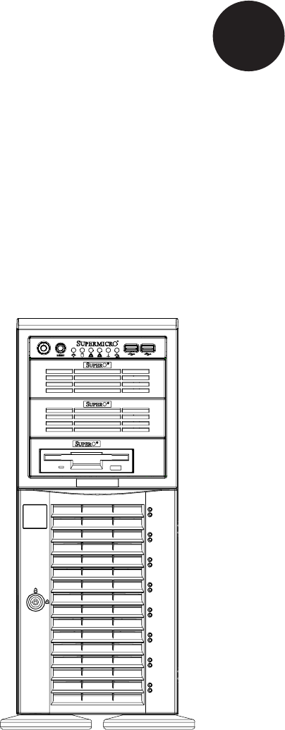
SuperWorkstation 7045A-C3/7045A-CT User's Manual Figure 6-1. Chassis Front View Main Power System Reset USB Ports 5.
Chapter 6: Advanced Chassis Setup 6-2 Front Control Panel The front control panel must be connected to the JF1 connector on the serverboard to provide you with system status and alarm indications. A ribbon cable has bundled these wires together to simplify this connection. Connect the cable from JF1 on the serverboard (making sure the red wire plugs into pin 1) to the appropriate comnnector on the front control panel PCB (printed circuit board).
SuperWorkstation 7045A-C3/7045A-CT User's Manual 6-3 System Fans Two 8-cm PWM chassis fans provide air intake while one 9-cm PWM exhaust fan expels hot air from the chassis. All are low-noise fans that result in very low system noise levels. The chassis is also fitted with an air shroud to concentrate the flow of cooling air through the system. The fans should be connected to headers on the serverboard (see Chapter 5). The power supply includes redundant cooling fans.
Chapter 6: Advanced Chassis Setup Figure 6-3.
SuperWorkstation 7045A-C3/7045A-CT User's Manual 6-4 Drive Bay Installation A total of eight SAS (or six SATA) drives may be housed in the SC743TQ-865-SQ chassis. The drive IDs are preconfigured as 0 through 7 (or 5) in order from bottom to top (or from left to right if rackmounted). A bezel covers the drive area but does not need to be removed to access the drives; simply swing open the bezel.
Chapter 6: Advanced Chassis Setup Figure 6-4. Removing a SAS/SATA Drive Carrier Figure 6-5. Mounting a SAS/SATA Drive in a Carrier Important! Use extreme caution when working around the SAS/ ! SATA backplane. Do not touch the backplane with any metal objects and make sure no ribbon cables touch the backplane or obstruct the airflow holes. SAS/SATA Backplane The SAS/SATA drives plug into a SAS/SATA backplane.
SuperWorkstation 7045A-C3/7045A-CT User's Manual Installing Components in the 5.25" Drive Bays The 7045A-C3/7045A-CT has two 5.25" drive bays. Components such as an extra floppy drive, IDE hard drives or CD-ROM drives can be installed into these 5.25" drive bays. Removing the Empty Drive Bay 1. First power down the system. 2. Remove the top/left chassis cover to access the drive components. 3.
Chapter 6: Advanced Chassis Setup 6-5 Power Supply The SuperWorkstation 7045A-C3/7045A-CT has a single 865 watt power supply. This power unit is equipped with low-noise technology, making the system ideal for workstation environments. The power supply has an auto-switching capability that enable it to automatically sense and operate with 100 or 240 volt inputs. Power Supply Failure If the power supply unit fails, the system will shut down and you will need to replace the power supply unit.
SuperWorkstation 7045A-C3/7045A-CT User's Manual Notes 6-10
Chapter 7: BIOS Chapter 7 BIOS 7-1 Introduction This chapter describes the Phoenix BIOS™ Setup utility for the X7DCA-3/X7DCA-i. The Phoenix ROM BIOS is stored in a flash chip and can be easily upgraded using a floppy disk-based program. Note: Due to periodic changes to the BIOS, some settings may have been added or deleted and might not yet be recorded in this manual. Please refer to the Manual Download area of the Supermicro web site for any changes to the BIOS that may not be reflected in this manual.
SuperWorkstation 7045A-C3/7045A-CT User's Manual 7-2 Running Setup Default settings are in bold text unless otherwise noted. The BIOS setup options described in this section are selected by choosing the appropriate text from the main BIOS Setup screen. All displayed text is described in this section, although the screen display is often all you need to understand how to set the options (see the next page). When you first power on the computer, the Phoenix BIOS™ is immediately activated.
Chapter 7: BIOS Main BIOS Setup Menu Main Setup Features System Time To set the system date and time, key in the correct information in the appropriate fields. Then press the key to save the data. System Date Using the arrow keys, highlight the month, day and year fields, and enter the correct data. Press the key to save the data. BIOS Date This field displays the date when this version of BIOS was built.
SuperWorkstation 7045A-C3/7045A-CT User's Manual IDE Primary Master/Slave, IDE Secondary Master/Slave, SATA Port3, SATA Port4 and Ext. Primary Master/Slave These settings allow the user to set the parameters of IDE Primary Master/Slave, IDE Secondary Master/Slave, SATA Port 3, SATA Port 4 and Ext. Primary Master/ Slave. Hit to activate the following sub-menu screen for detailed options of these items. Set the correct configurations accordingly.
Chapter 7: BIOS CHS Format (Available for Primary/Master only) The following items will be displayed by the BIOS: Type: This item displays the type of IDE or SATA Device. Cylinders: This item indicates the status of Cylinders. Headers: This item indicates the number of headers. Sectors: This item displays the number of sectors. Maximum Capacity: This item displays the maximum storage capacity of the system.
SuperWorkstation 7045A-C3/7045A-CT User's Manual Serial ATA This setting allows the user to enable or disable the Serial ATA function. The options are Disabled and Enabled. Native Mode Operation Select the native mode for ATA. The options are Parallel ATA, Serial ATA, Both and Auto. Serial ATA (SATA) RAID Enable Select Enable to enable Serial ATA RAID Functions. (For a Windows OS environment, use the RAID driver if this feature is set to Enabled.
Chapter 7: BIOS 7-4 Advanced Setup Choose Advanced from the Phoenix BIOS Setup Utility main menu with the ar- row keys. You should see the following display. The items with a triangle beside them have sub menus that can be accessed by highlighting the item and pressing . Boot Features Access the submenu to make changes to the following settings. QuickBoot Mode If enabled, this feature will speed up the POST (Power On Self Test) routine by skipping certain tests after the computer is turned on.
SuperWorkstation 7045A-C3/7045A-CT User's Manual ACPI Sleep Mode UThis feature allows you to decide which ACPI power management mode to use when in sleep mode. The options are S1, S3 and S1S3. Power Button Behavior If set to Instant-Off, the system will power off immediately as soon as the user hits the power button. If set to 4-sec., the system will power off when the user presses the power button for 4 seconds or longer. The options are instant-off and 4-sec override.
Chapter 7: BIOS will be reserved for Video BIOS ROM access only. Select Uncached to disable this function and make this area available for other devices. Cache Base 0-512K If enabled, this feature will allow the data stored in the base memory area: block 0-512K to be cached (written) into a buffer, a storage area in the Static DROM (SDROM) or to be written into the L1, L2 cache inside the CPU to speed up CPU operations. Select Uncached to disable this function.
SuperWorkstation 7045A-C3/7045A-CT User's Manual graphic effects when using a Linux graphic driver that requires the write-combining configuration with 4GB or more memory. The options are Enabled and Disabled. PCI Configuration Access the submenu to make changes to the following settings for PCI devices. Onboard GLAN1/Onboard GLAN2 (Gigabit- LAN) OPROM Configure Select Enabled to allow the system to boot from the GLAN1 connection or the GLAN 2 connection. The options are Disabled and Enabled.
Chapter 7: BIOS Advanced Chipset Control Access the submenu to make changes to the following settings. Warning: Use caution when changing the Advanced settings. Incorrect setup, a very high DRAM frequency or an incorrect DRAM timing may cause the system become unstable. If this occurs, reset the stting to the default setting. Crystal Beach Features Select Enabled to use Intel's I/O AT (Acceleration Technology) to accelerate the performance of TOE devices.
SuperWorkstation 7045A-C3/7045A-CT User's Manual USB Host Controller 2 Select Enabled to activate USB Host Controller 2. The settings are Enabled and Disabled. Legacy USB Support This setting allows you to enable support for Legacy USB devices. The settings are Enabled and Disabled. Advanced Processor Options Access the submenu to make changes to the following settings. CPU Speed This is a display that indicates the speed of the installed processor.
Chapter 7: BIOS Execute Disable Bit (Available when supported by the CPU and the OS) Set to Enabled to enable Execute Disable Bit and allow the processor to classify areas in memory where an application code can execute and where it cannot, and thus preventing a worm or a virus from inserting and creating a flood of codes to overwhelm the processor or damage the system during an attack. (This feature is only available if your OS and your CPU support the Execute Disable Bit function.
SuperWorkstation 7045A-C3/7045A-CT User's Manual CPU Cache Control Access the submenu to make changes to the following settings. Direct Cache Access (Available when supported by the CPU) Set to Enable to route inbound network IO traffic directly into processor caches to reduce memory latency and improve network performance. The options are Disabled and Enabled.
Chapter 7: BIOS Base I/O Address This setting allows you to select the base I/O address for serial port B. The options are 3F8, 2F8, 3E8 and 2E8. Interrupt This setting allows you to select the IRQ (interrupt request) for serial port B. The options are IRQ3 and IRQ4. Parallel Port This setting allows you to assign control of the parallel port. The options are Enabled (user defined), Disabled and Auto (BIOS or OS controlled). Base I/O Address Select the base I/O address for the parallel port.
SuperWorkstation 7045A-C3/7045A-CT User's Manual Event Log Validity This is a display to inform you of the event log validity. It is not a setting. Event Log Capacity This is a display to inform you of the event log capacity. It is not a setting. View DMI Event Log Highlight this item and press to view the contents of the event log. Event Logging This setting allows you to Enable or Disable event logging. ECC Event Logging This setting allows you to Enable or Disable ECC event logging.
Chapter 7: BIOS Console Connection This item allows you to decide how the console redirection is to be connected: either Direct or Via Modem. Continue CR after POST This item allows you to decide whether you want to continue with the console redirection after POST routines. The options are On and Off. Hardware Monitor Logic Note: The Phoenix BIOS will automatically detect the type of CPU(s) and hardware monitoring chip used on the motherboard and will display the Hardware Monitoring screen accordingly.
SuperWorkstation 7045A-C3/7045A-CT User's Manual Voltage Monitoring The following items will be monitored and displayed: Vcore A, Vcore B, -12V, +12V, P1V5, +3.3V, 5Vsb, 5VDD, P_VTT and Vbat Note: In a Windows OS environment, the Supero Doctor III settings take precedence over the BIOS settings. When first installed, Supero Doctor III adopts the temperature threshold settings previously set in the BIOS.
Chapter 7: BIOS Existing Event Log Number This item displays the number of the existing event log. Event Log Control System Firmware Progress Enable this function to log the POST progress. The options are Enabled and Disabled. BIOS POST Errors Enabling this function to log POST errors. The options are Enabled and Disabled. BIOS POST Watch Dog Set to Enabled to enable POST Watch Dog. The options are Enabled and Disabled. OS Boot Watch Dog Set to Enabled to enable OS Boot Watch Dog.
SuperWorkstation 7045A-C3/7045A-CT User's Manual Realtime Sensor Data This feature display information from motherboard sensors, such as temperatures, fan speeds and voltages of various components.
Chapter 7: BIOS 7-5 Security Choose Security from the Phoenix BIOS Setup Utility main menu with the arrow keys. You should see the following display. Security setting options are displayed by highlighting the setting using the arrow keys and pressing . All Security BIOS settings are described in this section. Supervisor Password Is: This indicates if a supervisor password has been entered for the system.
SuperWorkstation 7045A-C3/7045A-CT User's Manual Set User Password When the item Set User Password is highlighted, hit the key. When prompted, type the user's password in the dialogue box to set or to change the user's password, which allows access to the system at boot-up. Password on Boot This setting allows you to determine if a password is required for a user to enter the system at bootup. The options are Enabled (password required) and Disabled (password not required).
Chapter 7: BIOS 7-6 Boot Choose Boot from the Phoenix BIOS Setup Utility main menu with the arrow keys. You should see the following display. See details on how to change the order and specs of boot devices in the Item Specific Help window. All Boot BIOS settings are described in this section. Boot List Candidate List Boot Priority Order/Excluded from Boot Orders The devices included in the boot list section (above) are bootable devices listed in the sequence of boot order as specified.
SuperWorkstation 7045A-C3/7045A-CT User's Manual 7-7 Exit Choose Exit from the Phoenix BIOS Setup Utility main menu with the arrow keys. You should see the following display. All Exit BIOS settings are described in this section. Exit Saving Changes Highlight this item and hit to save any changes you made and to exit the BIOS Setup utility. Exit Discarding Changes Highlight this item and hit to exit the BIOS Setup utility without saving any changes you may have made.
Appendix A: BIOS POST Messages Appendix A BIOS POST Messages During the Power-On Self-Test (POST), the BIOS will check for problems. If a problem is found, the BIOS will activate an alarm or display a message. The following is a list of such BIOS messages. Failure Fixed Disk Fixed disk is not working or not configured properly. Check to see if fixed disk is attached properly. Run Setup. Find out if the fixed-disk type is correctly identified. Stuck key Stuck key on keyboard.
SuperWorkstation 7045A-C3/7045A-CT User's Manual System CMOS checksum bad - Default configuration used System CMOS has been corrupted or modified incorrectly, perhaps by an application program that changes data stored in CMOS. The BIOS installed Default Setup Values. If you do not want these values, enter Setup and enter your own values. If the error persists, check the system battery or contact your dealer. System timer error The timer test failed. Requires repair of system board.
Appendix A: BIOS POST Messages slows system performance considerably. CPU ID: CPU socket number for Multi-Processor error. EISA CMOS not writeable ServerBIOS2 test error: Cannot write to EISA CMOS. DMA Test Failed ServerBIOS2 test error: Cannot write to extended DMA (Direct Memory Access) registers. Software NMI Failed ServerBIOS2 test error: Cannot generate software NMI (Non-Maskable Interrupt). Fail-Safe Timer NMI Failed ServerBIOS2 test error: Fail-Safe Timer takes too long.
SuperWorkstation 7045A-C3/7045A-CT User's Manual I/O device IRQ conflict I/O device IRQ conflict error. PS/2 Mouse Boot Summary Screen: PS/2 Mouse installed. nnnn kB Extended RAM Passed Where nnnn is the amount of RAM in kilobytes successfully tested. nnnn Cache SRAM Passed Where nnnn is the amount of system cache in kilobytes successfully tested. nnnn kB Shadow RAM Passed Where nnnn is the amount of shadow RAM in kilobytes successfully tested.
Appendix A: BIOS POST Messages screen (usually an initialization error of an Option ROM, i.e., an add-on card). Write down and follow the information shown on the screen. Press to enter Setup Optional message displayed during POST. Can be turned off in Setup. PS/2 Mouse: PS/2 mouse identified. Run the I2O Configuration Utility One or more unclaimed block storage devices have the Configuration Request bit set in the LCT. Run an I2O Configuration Utility (e.g. the SAC utility).
SuperWorkstation 7045A-C3/7045A-CT User's Manual Notes A-6
Appendix B: BIOS POST Codes Appendix B BIOS POST Codes This section lists the POST (Power On Self Test) codes for the PhoenixBIOS. POST codes are divided into two categories: recoverable and terminal. Recoverable POST Errors When a recoverable type of error occurs during POST, the BIOS will display an POST code that describes the problem.
SuperWorkstation 7045A-C3/7045A-CT User's Manual POST Code Description 18h 8254 timer initialization 1Ah 8237 DMA controller initialization 1Ch 20h Reset Programmable Interrupt Controller 1-3-1-1 Test DRAM refresh 22h 1-3-1-3 Test 8742 Keyboard Controller 24h Set ES segment register to 4 GB 28h 29h Auto size DRAM Initialize POST Memory Manager 2Ah Clear 512 kB base RAM 2Ch 1-3-4-1 RAM failure on address line xxxx* 2Eh 1-3-4-3 RAM failure on data bits xxxx* of low byte of memory bus Enable c
Appendix B: BIOS POST Codes POST Code Description 5Ch Test RAM between 512 and 640 kB 60h Test extended memory 62h 64h Test extended memory address lines Jump to UserPatch1 66h Configure advanced cache registers 67h Initialize Multi Processor APIC 68h 69h Enable external and CPU caches Setup System Management Mode (SMM) area 6Ah Display external L2 cache size 6Bh Load custom defaults (optional) 6Ch 70h 72h 76h 7Ch 7Dh 7Eh 80h 81h 82h 83h 84h 85h 86h 87h 88h 89h 8Ah 8Bh 8Ch 8Fh 90h 91h 92h 93
SuperWorkstation 7045A-C3/7045A-CT User's Manual POST Code Description 99h Check for SMART Drive (optional) 9Ch Set up Power Management 9Dh 9Eh Initialize security engine (optional) Enable hardware interrupts 9Fh Determine number of ATA and SCSI drives A0h Set time of day A2h A4h Check key lock Initialize typematic rate A8h Erase prompt AAh Scan for key stroke ACh AEh B0h B1h B2h B4h B5h B6h B7h B9h BAh BCh BDh BEh BFh C0h C1h C2h C3h C4h C6h C7h C8h C9h CDh D2h D4h D8h D9h DEh
Appendix B: BIOS POST Codes The following are for boot block in Flash ROM POST Code Description E0h Initialize the chipset E1h Initialize the bridge E2h E3h Initialize the CPU Initialize system timer E4h Initialize system I/O E5h Check force recovery boot E6h E7h Checksum BIOS ROM Go to BIOS E8h E9h EAh EBh ECh EDh EEh EFh F0h F1h F2h F3h F4h F5h F6h F7h Set Huge Segment Initialize Multi Processor Initialize OEM special code Initialize PIC and DMA Initialize Memory type Initialize Memory size
SuperWorkstation 7045A-C3/7045A-CT User's Manual Notes B-6
Appendix C: Intel HostRAID Setup Guidelines Appendix C Intel HostRAID Setup Guidelines After all the hardware has been installed, you must first configure the Intel ICH9R SATA RAID* Settings before you install the Windows Operating System and other software drivers. Note: If you do not wish to configure onboard SATA RAID functions, please go directly to Section C-2 and Appendix E for the Operating System & Other Software Installation.
SuperWorkstation 7045A-C3/7045A-CT User's Manual RAID Configurations The following types of RAID configurations are supported: RAID 0 (Data Striping): this writes data in parallel, interleaved ("striped") sections of two hard drives. Data transfer rate is doubled over using a single disk. RAID 1 (Data Mirroring): an identical data image from one drive is copied to another drive. The second drive must be the same size or larger than the first drive.
Appendix C: Intel HostRAID Setup Guidelines Using the Intel ICH9R SATA RAID Utility Program 1. Creating, Deleting and Resetting RAID Volumes: a. After the system exits from the BIOS Setup Utility, the system will automatically reboot. The following screen appears after Power-On Self Test. b. When you see the above screen, press the and the keys simultaneously to have the main menu of the SATA RAID Utility appear: Note: All graphics and screen shots shown in the manual are for reference only.
SuperWorkstation 7045A-C3/7045A-CT User's Manual Creating a RAID 0 Volume: a. Select "Create RAID Volume" from the main menu and press the key. The following screen will appear: b. Specify a name for the RAID 0 set and press the key or the key to go to the next field. (You can use the key to select the previous menu.) c. When RAID Level item is highlighted, press the , keys to select RAID 0 (Stripe) and hit . d.
Appendix C: Intel HostRAID Setup Guidelines Creating a RAID 1 Volume: a. Select "Create RAID Volume" from the main menu and press the key. The following screen will appear: b. Specify a name for the RAID 1 set and press the key or the key to go to the next field. (You can use the key to select the previous menu.) c. When RAID Level item is highlighted, press the , keys to select RAID 1 (Mirror) and hit . d.
SuperWorkstation 7045A-C3/7045A-CT User's Manual Creating a RAID 10 (RAID 1+ RAID 0): a. Select "Create RAID Volume" from the main menu and press the key. The following screen will appear: b. Specify a name for the RAID 10 set and press . c. When RAID Level item is highlighted, use the , keys to select RAID 10 (RAID1 + RAID0) and hit . d.
Appendix C: Intel HostRAID Setup Guidelines Creating a RAID 5 Set (Parity): a. Select "Create RAID Volume" from the main menu and press the key. The following screen will appear: b. Specify a name for the RAID 5 set and press . c. When the Raid Level is highlighted, use the , keys to select RAID 5 (Parity) and hit . d. When the Disk item is highlighted, press to select the HDD to configure as RAID.
SuperWorkstation 7045A-C3/7045A-CT User's Manual Deleting RAID Volume: Warning: Be sure to back up your data before deleting a RAID set. You will lose all data on the disk drives when deleting a RAID set.) a. From the main menu, select item2-Delete RAID Volume, and press . b. Use the , keys to select the RAID set you want to delete and press . A Warning message displays. c.
Appendix C: Intel HostRAID Setup Guidelines Resetting to Non-RAID and Resetting a RAID HDD Warning: Be cautious when you reset a RAID volume HDD to nonRAID or Resetting a RAID HDD. Resetting a RAID volume HDD or Resetting a RAID HDD will reformat the HDD and delete all internal RAID structure on the drive. a. From the main menu, select item3-Reset Disks to Non- RAID, and press . The following screen will appear: b.
SuperWorkstation 7045A-C3/7045A-CT User's Manual C-2 Installing Windows XP/2000/2003 for RAID Systems Installing a New Operating System-the Windows XP/2000/2003 OS a. Insert Microsoft's Windows XP/2000/2003 Setup CD in the CD Driver, and the system will start booting up from CD. b. Press the key when the message-" Press F6 if you need to install a third party SCSI or RAID driver" displays. c. When the Windows XP/2000/2003 Setup screen appears, press "S" to specify additional device(s). d.
Appendix D: System Specifications Appendix D System Specifications Processors Single or dual Intel® dual-core Xeon® 5400/5300/5200/5100 Sequence type processors at a front side (system) bus speed of 1333/1066 MHz Note: Please refer to our web site for a complete listing of supported processors.
SuperWorkstation 7045A-C3/7045A-CT User's Manual Expansion Slots One PCI-Express x16, one PCI-Express x4 (in a x16 slot), two 64-bit 133/100 MHz PCI-X, two PCI 33 MHz and an IPMI slot Motherboard 7045A-C3: X7DCA-3 (Extended ATX form factor) 7045A-CT: X7DCA-i (Extended ATX form factor) Dimensions (both): 12 x 13 in (305 x 330 mm) Chassis SC743TQ-865-SQ Form Factor: tower/4U rackmount Dimensions (as tower): (WxHxD) 7 x 17.2 x 25.5 in. (178 x 437 x 648 mm) Weight Gross (Bare Bone): 64 lbs. (29.1 kg.
Appendix D: System Specifications Regulatory Compliance Electromagnetic Emissions: FCC Class B, EN 55022 Class B, EN 61000-3-2/-3-3, CISPR 22 Class B Electromagnetic Immunity: EN 55024/CISPR 24, (EN 61000-4-2, EN 61000-4-3, EN 61000-4-4, EN 61000-4-5, EN 61000-4-6, EN 61000-4-8, EN 61000-4-11) Safety: EN 60950/IEC 60950-Compliant, UL Listed (USA), CUL Listed (Canada), TUV Certified (Germany), CE Marking (Europe) California Best Management Practices Regulations for Perchlorate Materials: This Perchlorate war
SuperWorkstation 7045A-C3/7045A-CT User's Manual Notes D-4