
user manual

2-8
X6DAT-G/X6DAi-G User's Manual
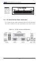
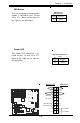
ATX Power Supply 24-pin Connector
Pin Definitions (J1B4)
Pin Number Definition
13 +3.3V
14 -12V
15 COM
16 PS_ON#
17 COM
18 COM
19 COM
20 Res(NC)
21 +5V
22 +5V
23 +5V
24 COM
Pin Number Definition
1 +3.3V
2 +3.3V
3 COM
4 +5V
5 COM
6 +5V
7 COM
8 PWR_OK
9 5VSB
10 +12V
11 +12V
12 +3.3V
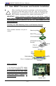
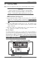
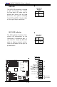
2-5 Connecting Cables
ATX Power Connector
There are a 24-pin main power
supply connector(PW1:J1B4) and
a 4-pin CPU PWR connector (J32)
on the board. These power con-
nectors meet the SSI EPS 12V
specification. Both power con-
nectors are required to ensure
sufficient power supply. See the
table on the right for pin defini-
tions. For CPU PWR (J1D1), please
refer to the item listed below.
Pins
1 thru 4
5 thru 8
Definition
Ground
+12v
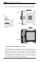
CPU 8-Pin PWR
Connector (J1D1)
Processor Power
Connector
In addition to the Primary ATX
power connector (above), the 12v
8-pin Processor connector at J1D1
must also be connected to your
power supply. See the table on
the right for pin definitions.
Pins #
1 & 2
3 & 4
Definition
Ground
+12 V
+12V 4-pin
Connector
(J32)
Required
Connection
Required
Connection
K B /
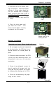
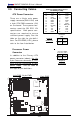
Mouse
DIMM 4A
DIMM 4B
DIMM 3A
DIMM 3B
DIMM 2A
DIMM 2B
DIMM 1A
DIMM 1B
S PKR
Tumwater
(North
B ridge)
(S outh
Bridge)
IDE #1
IDE #2
Floppy
Fan4
U SB2/ 3
JD2
J
F
1
FAN7
CPU1
CPU2
J
D
1
J 2 4
USB
0/1
JL A
N
1
CO
M2
CO
M1
Parrallel
Port
Fan6
Fan5
J 32
4-pin
PWR
Bank 1
Bank 1
Bank 2
Bank 2
Bank 3
Bank 3
Bank 4
Bank 4
ATX PWR
J1B 4
JPF
Force
PW
JLAN1
Line_In/
Line_Out
JPAC
S
I/O
x1
6 PCI EXP #
6
PCI #
5-33M
Hz
PCI#
3- 33M
Hz
PCIX#
2- 66M
Hz
J 2
7
C
D
1
C
D
2
PCIX#1-
66M
Hz ZCR
GLAN
CTRL
JWOR
SMB
us
J 2
2
Fan3
JK
1
FAN1
J1D1
JC2
M ic
JC1
x8 PC
I EXP #4
JWOL
JL1
JAR
JOH1
JP1
5
JP12
Marvell
FAN2
JWD
SATA0
SATA1 SATA0
SATA1
SATA2
Marvell's
SATA3
SATA
ACT
LED
Battery
SATAI
2
C
JPS1
F
a
n
8
BIOS
JPL1
J
B
T
1
6041
6300E SB
JP13
Intel's
D
S
1
D
S
9
D
S
2
D
S
1
0
D
S
3
D
S
1
1
D
S
4
D
S
1
2
J40
J 23
4-pin PWR
24-pin PWR
12-pin PWR