SUPER ® SC743 Chassis Series SC743TQ-865B-SQ SC743TQ-865(B) SC743TQ-R760(B) SC743S2-R760(B) SC743S1-R760(B) SC743T-R760(B) SC743i-R760(B) SC743i-665B SC743T-665B SC743i-500B SC743T-500B SC743i-465B USER’S MANUAL 1.
SC743 Chassis Manual The information in this User’s Manual has been carefully reviewed and is believed to be accurate. The vendor assumes no responsibility for any inaccuracies that may be contained in this document, makes no commitment to update or to keep current the information in this manual, or to notify any person or organization of the updates. Please Note: For the most up-to-date version of this manual, please see our web site at www.supermicro.com. Super Micro Computer, Inc.
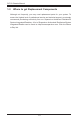
Preface Preface About This Manual This manual is written for professional system integrators and PC technicians. It provides information for the installation and use of the SC743 chassis. Installation and maintenance should be performed by experienced technicians only. Supermicro’s SC743 chassis features a unique and highly-optimized design. The chassis is equipped with a 465, 500, 665, 760 or 865 Watt power supply, and highperformance fans provide ample optimized cooling.
SC743 Chassis Manual Manual Organization Chapter 1: Introduction The first chapter provides a checklist of the main components included with this chassis and describes the main features of the SC743 chassis. This chapter also includes contact information. Chapter 2: System Safety This chapter lists warnings, precautions, and system safety. It recommended that you thoroughly familiarize yourself installing and servicing this chassis safety precautions.
Preface Table of Contents Chapter 1 Introduction 1-1 Overview.......................................................................................................... 1-1 1-2 Shipping List..................................................................................................... 1-1 Part Numbers................................................................................................... 1-1 1-3 Where to get Replacement Components........................................................
SC743 Chassis Manual Standard Cooling Systems.............................................................................. 4-9 4-8 Removing the Air Shroud................................................................................4-11 4-9 Installing the Motherboard............................................................................. 4-12 4-10 Installing Expansion Cards............................................................................ 4-14 4-11 Power Supply.....................
Chapter 1: Introduction Chapter 1 Introduction 1-1 Overview Supermicro’s SC743 chassis features a unique and highly-optimized design. The chassis is equipped with a high-efficiency 80%+ low-noise power supply. 1-2 Shipping List Part Numbers Please visit the the Supermicro Web site for the latest shiping lists and part numbers for your particular chassis model at http://www.supermicro.
SC743 Chassis Manual 1-3 Where to get Replacement Components Although not frequently, you may need replacement parts for your system. To ensure the highest level of professional service and technical support, we strongly recommend purchasing exclusively from our Supermicro Authorized Distributors/ System Integrators/Resellers. A list of Supermicro Authorized Distributors/System Integrators/Reseller can be found at: http://www.supermicro.com. Click the Where to Buy link.
Chapter 1: Introduction 1-4 Contacting Supermicro Headquarters Address: Super Micro Computer, Inc. 980 Rock Ave. San Jose, CA 95131 U.S.A. Tel: +1 (408) 503-8000 Fax: +1 (408) 503-8008 Email: marketing@supermicro.com (General Information) support@supermicro.com (Technical Support) Web Site: www.supermicro.com Europe Address: Super Micro Computer B.V. Het Sterrenbeeld 28, 5215 ML 's-Hertogenbosch, The Netherlands Tel: +31 (0) 73-6400390 Fax: +31 (0) 73-6416525 Email: sales@supermicro.
SC743 Chassis Manual 1-5 Returning Merchandise for Service A receipt or copy of your invoice marked with the date of purchase is required before any warranty service will be rendered. You can obtain service by calling your vendor for a Returned Merchandise Authorization (RMA) number. When returning to the manufacturer, the RMA number should be prominently displayed on the outside of the shipping carton, and mailed prepaid or hand-carried.
Chapter 2: System Safety Chapter 2 System Safety 2-1 Overview This chapter provides a quick setup checklist to get your chassis up and running. Following the steps in the order given should enable you to have your chassis set up and operational within a minimal amount of time. This quick setup assumes that you are an experienced technician, familiar with common concepts and terminology.
SC743 Chassis Manual 2-4 Electrical Safety Precautions Basic electrical safety precautions should be followed to protect yourself from harm and the SC743 from damage: • • • • • • • • Be aware of the locations of the power on/off switch on the chassis as well as the room’s emergency power-off switch, disconnection switch or electrical outlet. If an electrical accident occurs, you can then quickly remove power from the system. Do not work alone when working with high-voltage components.
Chapter 2: System Safety • Please handle used batteries carefully. Do not damage the battery in any way; a damaged battery may release hazardous materials into the environment. Do not discard a used battery in the garbage or a public landfill. Please comply with the regulations set up by your local hazardous waste management agency to dispose of your used battery properly. • 2-5 • • • • • 2-6 DVD-ROM laser: CAUTION - This server may have come equipped with a DVD-ROM drive.
SC743 Chassis Manual • Use a grounded wrist strap designed to prevent static discharge. • Keep all components and printed circuit boards (PCBs) in their antistatic bags • • • • • • until ready for use. Touch a grounded metal object before removing any board from its antistatic bag. Do not let components or PCBs come into contact with your clothing, which may retain a charge even if you are wearing a wrist strap.
Chapter 3: Chassis Components Chapter 3 Chassis Components 3-1 Overview This chapter describes the most common components included with your chassis. Some components listed may not be included or compatible with your particular chassis model. For more information, see the installation instructions detailed later in this manual. 3-2 Components Chassis The SC743 chassis may include the following options: • Up to three 5.25" peripheral bays • Up to eight 3.5" hard drives.
SC743 Chassis Manual 3-3 Where to get Replacement Components Although not frequently, you may need replacement parts for your system. To ensure the highest level of professional service and technical support, we strongly recommend purchasing exclusively from our Supermicro Authorized Distributors/ System Integrators/Resellers. A list of Supermicro Authorized Distributors/System Integrators/Resellers can be found at: http://www.supermicro.com.
Chapter 3: Chassis Components 3-5 Control Panel Buttons There are two push-buttons located on the front of the chassis. These are (in order from left to right) a power on/off button and a reset button. • • 3-6 Power: The main power switch is used to apply or remove power from the power supply to the server system. Turning off system power with this button removes the main power but keeps standby power supplied to the system. Therefore, you must unplug system before servicing.
SC743 Chassis Manual • HDD: Indicates IDE channel activity. SAS/SATA drive, SCSI drive, and/or DVDROM drive activity when flashing. • NIC1: Indicates network activity on GLAN1 when flashing. • NIC2: Indicates network activity on GLAN2 when flashing. • Overheat/Fan Fail: When this LED flashes it indicates a fan failure.
Chapter 3: Chassis Components ! • Power Fail: Indicates a power failure to the system's power supply units.
SC743 Chassis Manual Notes 3-6
Chapter 4: Chassis Setup and Maintenance Chapter 4 Chassis Setup and Maintenance 4-1 Overview This chapter covers the steps required to install components and perform maintenance on the chassis. The only tool you will need to install components and perform maintenance is a Phillips screwdriver. Print this page to use as a reference while setting up your chassis. The SC743 i series chassis models do not come equipped with hot-swappable hard drives.
SC743 Chassis Manual 4-2 Removing the Chassis Side and Top Covers Disconnecting the Chassis from the Power Source 1. Turn off all peripheral devices and turn off the power supply to the SC743. 2. Disconnect the AC power cords from the system. 3. Disconnect all cables and label the cables for easy identification. ! Warning: Use a grounded wrist strap designed to prevent static discharge when handling components. Removing the Side Cover Removing the Side Cover of the Chassis 1.
Chapter 4: Chassis Setup and Maintenance When mounting the SC743 into a rack or changing the power supply, it is necessary to remove the top cover from the chassis. Removing the Top Cover Removing the Top Cover of the Chassis 1. Disconnect the chassis from any power source. 2. Press the release tab at the back of the top cover. 3. Slide the back cover off the chassis.
SC743 Chassis Manual 4-3 Accessing the Hot-Swappable Drive Carriers Hot-swappable drives may be removed and installed in the chassis without powering-down the system and without opening the chassis cover. Accessing and Removing Hard Drive Carriers 1. Unlock and open the drive carrier door as shown. 2. Press the release tab located on the drive carrier. This will release the drive carrier from its locked position. 3. Lift up the drive carrier handle. 4.
Chapter 4: Chassis Setup and Maintenance 4-4 Installing Hard Drives into the Drive Carriers Installing Hard Drives 1. Remove the screws from the hard drive carrier and set them aside for later use. 2. Remove the dummy drive from the hard drive carrier. 3. Mount a hard drive into the hard drive carrier 4. Replace the screws which were set aside earlier. 5. Install the hard drive into the chassis. 6. Push down the release tab over the newly installed hard drive. 7. Close the hard drive carrier door.
SC743 Chassis Manual 4-5 Installing Fixed Hard Drives in SC743i Series Chassis Models The SC743i series chassis features dual fixed storage modules. The system must be powered-down and disconnected from any power source before installing or removing hard drives. Disconnecting the Chassis from the Power Source 1. Turn off all peripheral devices and turn off the power supply to the SC743. 2. Disconnect the AC power cord from the system. 3. Disconnect all cables and label the cables for easy identification.
Chapter 4: Chassis Setup and Maintenance 4-6 Configuring the Storage Module Storage Module Options The storage module can be configured to accommodate a variety of data storage devices such as CD, IDE, DVD and floppy drives. The chassis may be rotated from a vertical tower position, to a horizontal rack mounting position to accommodate use of these devices. The following configurations may be used in the SC743 chassis: • • • • 5.25" Drives: Install any combination of three 5.25" devices. 3.
SC743 Chassis Manual Configuring the Storage Module for 5.25" Devices 1. Remove the 5.25” drive carriers from the storage module. 2. Remove the screws and drive carrier brackets from the drive carriers. 3. Install the 5.25” devices into the storage module. 4. Replace the module back into the chassis. 5. Ensure that the storage module is securely locked into position. Figure 4-7: Installing 5.25" Devices into the Storage Module Configuring the Storage Module for 3.5" Devices with a Mobile Rack 1.
Chapter 4: Chassis Setup and Maintenance 4-7 Removing and Replacing the System Fans Before installing the motherboard in the chassis or accessing the motherboard after installation, it is necessary to remove the system fans. One set is located at the rear of the chassis, the other set is located in the middle of the chassis.
SC743 Chassis Manual Removing Rear Chassis Fans 1. Locate the release tab on the top of the chassis fan, at the rear of the chassis. Push the release tab down to unlock the fan. 2. Once the fan is unlocked, tip it forward and out of the chassis. 3. When replacing the rear chassis fan, push the fan back into the fan module until a click is heard, indicating that the fan has locked into position.
Chapter 4: Chassis Setup and Maintenance 4-8 Removing the Air Shroud Before installing the motherboard in the chassis or accessing the motherboard after installation, it is necessary to remove the air shroud between the two sets of system fans. SC743TQ-865B-SQ model chassis are equipped with a specialized air shroud to accommodate the super quiet front and rear fans.
SC743 Chassis Manual 4-9 Installing the Motherboard Prior to Installing the Motherboard Before the motherboard can be installed or removed, the air shroud must be removed, as directed in sections 4-8. The following information is for reference only, the motherboard is not included with the SC743 chassis.
Chapter 4: Chassis Setup and Maintenance 6. Secure the heatsink to the motherboard as directed by the motherboard documentation. 7. Secure the motherboard to the chassis using Type A screws, which are included in the chassis accessory kit. Do not exceed eight pounds of torque per square inch when tightening down the motherboard. 8. Replace the middle and rear system fans as directed in section 4-6. 9. Replace the air shroud as directed in section 4-7.
SC743 Chassis Manual 4-10 Installing Expansion Cards After installing the motherboard, expansion cards may be installed into the chassis. Installing Expansion Cards 1. Locate the release tab on the top of the PCI slot bracket 2. Gently apply pressure on the middle of the release tab to unlock the bracket as shown.
Chapter 4: Chassis Setup and Maintenance 3. Once the bracket is unlocked, pull the release tab upward and remove the bracket from the chassis. 4. Gently slide the expansion card bracket into the PCI slot until it clicks into place.
SC743 Chassis Manual 4-11 Power Supply The SC743 chassis includes a power supply rated at either 465, 500, 665, 760 or 865 Watts. In the unlikely event that you need to replace the power supply, simply follow the directions for your specific power supply below. ! Warning: Always unplug the power cord before removing the power supply. Warning: Do not open the casing of the power supply. Power supplies can only be serviced by a qualified manufacturer's technician.
Chapter 4: Chassis Setup and Maintenance 3 Remove Screws 14 Figure 4-15: Removing the Interior Chassis Screws on the Power Supply 3. Using a Phillips head screwdriver, remove the five screws securing the power supply to the chassis as shown above, and set them aside for later use. 4. Carefully lift the power supply up and out of the chassis. 5. Install the replacement power supply in the chassis. 6. Replace the screws which were set aside previously. 7.
SC743 Chassis Manual 760 Watt Power Supply The 760 Watt power supply is a triple redundant power supply with a different configuration than that of the 465, 500, 665 and 865 Watt power supplies. Installing the Power Supply 1. Unplug the AC power cord from the power supply. 2. Push the release tab on the left side of each power supply to release it from the locked position. 3. Once released from the locked position, pull the power supply outward, using the handle provided. 4.
Chapter 4: Chassis Setup and Maintenance 4-12 Accessing the Interior Space Between the Backplane and the Midplane For easy access to the interior space between the backplane and the midplane, follow the instructions below before installing components or cables into this area. Accessing the Interior Space 1. Remove the two screws as shown below and set them aside for future use. 2. Remove the three screws on the bottom of the bracket between the back plane and the mideplane. 3.
SC743 Chassis Manual 4-13 SCSI (Super) GEM Driver Installation Instructions for Windows OS Note: This driver is not necessary for other operating systems. If you have two SCA backplanes, you will need to install the driver twice. The driver is located on the Super Micro motherboard driver CD or may be downloaded from the Supermicro ftp site: ftp://ftp.supermicro.com/driver/Qlogic/ Follow the procedure below to install this driver onto your system. Installing the Driver 1.
Chapter 4: Chassis Setup and Maintenance Installing the Driver (Alternative Procedure) 1. Right click the “My Computer” icon on your desktop and choose Properties. 2. Click on the Hardware tab and select Device Manager to bring up the list of system devices. 3. You may see one or two yellow question marks (?) that read QLogic GEM354 or GEM318 SCSI Processor Device. Right click on these, and select uninstall. If two such question marks are present, uninstall both. 4.
SC743 Chassis Manual Notes 4-22
Chapter 5: Rack Installation Chapter 5 Rack Installation 5-1 Overview This chapter provides instructions on installing the chassis into a rack. Following these steps in the order given should enable you to have the system installed in a minimal amount of time. 5-2 Unpacking the System You should inspect the box the chassis was shipped in, and note if it was damaged in any way. If the chassis itself shows damage, you should file a damage claim with the carrier who delivered it.
SC743 Chassis Manual • This product is only to be installed in a Restricted Access Location (dedicated equipment rooms, service closets and similar environments). ! Warnings and Precautions! ! Rack Precautions • Ensure that the leveling jacks on the bottom of the rack are fully extended to the floor with the full weight of the rack resting on them. • In single rack installation, stabilizers should be attached to the rack. • In multiple rack installations, the racks should be coupled together.
Chapter 5: Rack Installation Rack Mounting Considerations Ambient Operating Temperature If installed in a closed or multi-unit rack assembly, the ambient operating temperature of the rack environment may be greater than the ambient temperature of the room. Therefore, consideration should be given to installing the equipment in an environment compatible with the manufacturer’s maximum rated ambient temperature (TMRA).
SC743 Chassis Manual 5-4 Installing the Chassis Rack Mounting Rails Before Installing the Chassis Rails 1. Unplug the power cord from the from the power supply. 2. Secure the chassis cover. 3. Remove all external devices and connectors. Installing the Inner Chassis Rails 1. Locate the pair of inner rails and two sets of screws (6 screws per set) that are included in the shipping package. 2. Remove the chassis feet and top cover. 3. Align the inner rails against the chassis as shown.
Chapter 5: Rack Installation Installing the Outer Chassis Rails 1. Locate the two pairs of outer rails. Each pair consists of one middle rail, one end bracket and one end rail as shown. Middle Rail End Rail End Bracket Figure 5-2: Assembling the Outer Chassis Rails 2. Insert the end bracket and the end rail onto the middle rail and secure them with the screws as shown. 3. Install a set of outer rail assemblies to each side of the rack and secure them with the screws provided. 4.
SC743 Chassis Manual Outer Rail Assemblies Inner Rails Figure 5-3: Mounting the Chassis into a Rack 5-6
Appendix A: Chassis Cables Appendix A Cables, Screws, and other Accessories A-1 Overview This appendix lists supported cables for your chassis system. It only includes the most commonly used components and configurations. For more compatible cables, refer to the manufacturer of the motherboard you are using and to the Supermicro Web site at: www.supermicro.com.
SC743 Chassis Manual SC743T Series (SAS/SATA) Part # Type Length Description CBL-0044L Cable 2' CBL-0087 Cable 20" Round 16-pin to 16-pin front panel ribbon cable CBL-0084 Cable 6" Split converter cable CBL-0062L Cable 7.9" CBL-0209L; Cable 8.
Appendix A: Chassis Cables Extending Power Cables Although Supermicro chassis are designed with to be efficient and cost-effective, some compatible motherboards have power connectors located in different areas. To use these motherboards you may have to extend the power cables to the mother boards. To do this, use the following chart as a guide. Power Cable Extenders Number of Pins Cable Part # Length 24-pin CBL-0042 7.9”(20 cm) 20-pin CBL-0059 7.9”(20 cm) 8-pin CBL-0062 7.
SC743 Chassis Manual A-3 Chassis Screws The accessory box includes all the screws needed to set up your chassis. This section lists and describes the most common screws used. Your chassis may not require all the parts listed. M/B HARD DRIVE Flat head 6-32 x 5 mm [0.197] Pan head 6-32 x 5 mm [0.197] DVD-ROM, CD-ROM, and FLOPPY DRIVE Pan head 6-32 x 5 mm [0.197] Flat head 6-32 x 5 mm [0.197] Round head M3 x 5 mm [0.197] Round head M2.6 x 5 mm [0.197] RAIL Flat head M4 x 4 mm [0.
Appendix B: Power Supply Specifications Appendix B Power Supply Specifications B-1 Power Supply Options This appendix lists power supply specifications for your chassis system. 465W MFR Part # PWS-465-PQ Rated AC Voltage 100 - 240V 60 - 50Hz 6 - 3 Amp +5V standby 3 Amp +12V 35 Amp +5V 20 Amp +3.3V 15 Amp -12V 0.5 Amp 500W MFR Part # PWS-502-PQ Rated AC Voltage 100 - 240V 50 - 60Hz 12 - 6 Amp +5V standby 6.5 Amp +12V 69 Amp +5V 30 Amp +3.
SC743 Chassis Manual 665W MFR Part # PWS-665-PQ Rated AC Voltage 100 - 240V 50 - 60Hz 10- 5 Amp +5V standby 6 Amp +12V 54.0 Amp +5V 30.0 Amp +3.3V 24 Amp -12V 0.5 Amp R760W MFR Part # PWS-0056 Rated AC Voltage 100 - 240V 50 - 60Hz 14 - 8 Amp +5V standby 3.5 Amp +12V 50.0 Amp +5V 36.0 Amp +3.3V 36.0 Amp -12V 1.0 Amp 865W MFR Part # PWS-865-PQ Rated AC Voltage 100 - 240V 50 - 60Hz 12- 6 Amp +5V standby 6.5 Amp +12V 70.0 Amp +5V 30.0 Amp +3.3V 30.0 Amp -12V 1.
Apppendix C: CSE-M34S/CSE-M34T Mobile Rack Specifications Appendix C CSE-M34S/CSE-M34T Mobile Rack Specifications C-1 Overview This manual is written for system integrators, PC technicians and knowledgeable PC users. It provides detailed information for the installation and use of the CSE-M34S/CSE-M34T mobile rack. The Supermicro CSE-M34S/CSE-M34T mobile rack offers cutting edge technolgy with greater flexibility. The CSE-M34T supports 4 Serial ATA hot-swappagle hard drives.
SC743 Chassis Manual C-3 Packing List The CSE-M34S/CSE-M34T mobile rack provides the following: • CSE-M34S/CSE-M34T mobile rack • 90 mm exhaust fan • Drive carrier four CSE-PT10 (-beige only) • Six counts of 6-32 hex washer head screws • Eight counts of M3 washer head screws • Eighteen counts of pan head screws For CSE-M34T only • Serial ATA backplane (CSESATA-M34) • Four Serial ATA cables (CBL-0044) • Serial ATA LED cable (CBL-0057) • SCSI cable (CBL-027-U320) • SCSI backplane (CSES
Apppendix C: CSE-M34S/CSE-M34T Mobile Rack Specifications Additional Information The CSE-M34S/CSE-M34T mobile rack was designed for use in certain chassis and servers or as a stand alone unit. Use the chassis or server manual for installation instructions. Use the instructions listed in this manual to use the mobile rack independent of a chassis. The pictures or graphics shown in this user’s guide were based upon the latest PCB revision available at the time of the publishing of this manual.
SC743 Chassis Manual C-4 Front Connectors and Jumpers JP24 JP14 JP25 JP21 JP18 Figure C-1.
Apppendix C: CSE-M34S/CSE-M34T Mobile Rack Specifications JP25 Overheat Temperature Open: 45 degrees Celcius 1-2: 50 degrees Celcius (Default) 2-3: 55 degrees Celcius JP26 Common Act#1-Act#4 Connect this header to CBL-0057 (SATA LED Cable) JP27 Common Act In-Act#1 Closed: Enable Open: Disable (default) JP28 Fan Sense 1-2: Enabled (if a fan is not present, the alarm will sound) (default) 2-3: Disabled JP29 Common Act In-Act#2 Closed: Enable Open: Disable (default) JP30 Common Act In-Act#3 Cl
SC743 Chassis Manual Jumper Settings and Locations for the CSE-M35T (SATA) Figure C-2: Jumper Locations JP25 JP18 Channel #1 Channel #2 Channel #3 Channel #4 JP28 Activity LEDs Pin Definitions JP26 ACT1 Act. LED1 = Channel 1 JP26 ACT2 ACT3 ACT4 COM Act. LED2 = Channel 2 Act. LED3 = Channel 3 Act.
Apppendix C: CSE-M34S/CSE-M34T Mobile Rack Specifications Installation Procedures Installing the CSE-M35S Backplane 1. SCSI IDs are assigned automatically by the backplane. Do not set IDs manually on the drives. See the previous section for SCSI ID jumper settings. 2. SCSI termination is enabled by default on the SCSI backplane. Accessing Hot-Swappable Drives 1. Push the release button located beside each drive's LED. 2. Lift up on the drive's handle. 3. Carefully pull the drives out of the storage module.
SC743 Chassis Manual Installing a Drive into the Drive Tray 1. Mount the drive in the drive tray. 2. Secure it into the drive tray as shown with the screws provided. Figure C-5: Installing the Drive into the Drive Tray ! Warning! Enterprise level hard disk drives are recommended for use in Supermicro chassis and servers. For information on recommended HDDs, visit the Supermicro Web site at http://www. supermicro.com/products/nfo/files/storage/SAS-1-CompList110909.
Apppendix C: CSE-M34S/CSE-M34T Mobile Rack Specifications Accessing the Backplane 1. Remove the screws located on the back of the mobile rack unit as shown 1 1 2. Pull out the rear fan bracket. 2 2 3. Remove the screws securing the backplane. 3 4 4. Remove the backplane.
SC743 Chassis Manual Notes C-10
Appendix D: M35TQ Mobile Rack Specifications Appendix D M35TQ Mobile Rack Specificaitons D-1 Overview This manual is written for system integrators, PC technicians and knowledgeable PC users who intend to integrate Supermicro's intelligent, highly expandable and costeffective mobile rack solutions into their systems. It provides the user with detailed information for the installation and use of the M35TQ mobile rack.
SC743 Chassis Manual D-3 An Important Note to the User The pictures or graphics shown in this User's Guide were based upon the latest PCB revision available at the time of the publishing of this manual. The M35TQ mobile rack you've received may or may not look exactly the same as the graphics shown in this manual. D-4 ESD Safety Guidelines Electrostatic Discharge (ESD) can damage electronic components. To prevent damage to your system, it is important to handle it very carefully.
Appendix D: M35TQ Mobile Rack Specifications • Make sure that the mobile rack is securely and properly installed on the motherboard to prevent damage to the system due to power shortage. D-6 Introduction to the SAS-M35TQ Backplane The M35TQ mobile rack contains a SAS-M35TQ backplane. The SAS-M35TQ backplane has been designed to utilize the most up-to-date technology available, providing your system with reliable, high-quality performance. This manual reflects SAS-M35TQ Revision 1.
SC743 Chassis Manual D-7 Front Connectors and Jumpers 1 S UPER 13 12 R 1 SASM35TQ 18 15 REV 1.01 14 17 111 12 1 13 1 14 1 15 1 16 19 10 1 Figure D-1: Front Connectors Front Connectors 1. 4-pin Power Connectors: JP10 and JP13 8. Upgrade: JP46 9. ACT IN: JP26 2. MG9072 Chip 10. Fan Connector: JP22 3. JTAG Connector: JP47 11. SAS Port #0: J5 4. I2C Connector #1: JP44 12. SAS Port #1: J6 5. I2C Connector #2: JP45 13. SAS Port #2: J7 6. Sideband Connector #1: JP51 14. SAS Port #3: J8 7.
Appendix D: M35TQ Mobile Rack Specifications D-8 Front Connectors and Pin Definitions 1. Mobile Rack Main Power Connectors The 4-pin power connectors, designated JP10 and JP13, provide power to the mobile rack. See the table on the right for pin definitions. Mobile rack Main Power 4-Pin Connector Pin# Definition 1 +12V 2 and 3 4 Ground +5V 2. MG9072 Chip The MG9072 is an enclosure management chip that supports the SES-2 controller and SES-2 protocols. 3.
SC743 Chassis Manual 6. and 7. Sideband Headers Sideband Headers The sideband headers are designated JP51 and JP52. For SES-2 to work properly, an 8-pin sideband cable must be connected. See the table to the right for pin definitions. Pin # Definition Pin # Definition 2 Mobile rack Addressing (SB5) 1 Controller ID (SB6) 4 Reset (SB4) 3 GND (SB2) 6 GND (SB3) 5 SDA (SB1) 8 Mobile rack ID (SB7) 7 SCL (SB0) 10 No Connection 9 No Connection 8.
Appendix D: M35TQ Mobile Rack Specifications D-9 Front Jumper Locations and Pin Definitions S UPER R SASM35TQ REV 1.01 S UPER JP62 JP38 JP29 R SASM35TQ JP50 JP37 JP36 JP41 JP33 REV 1.01 JP34 JP40 JP43 JP61 JP42 JP18 Figure D-2: Front Jumpers Explanation of Jumpers To modify the operation of the mobile rack, jumpers can be used to choose between optional settings.Jumpers create shorts between two pins to change the function of the connector.
SC743 Chassis Manual S UPER R SASM35TQ S UPER JP29 REV 1.01 R SASM35TQ REV 1.01 JP18 Figure D-3: Buzzer and Chip Reset Jumpers Buzzer and Chip Reset Jumper Settings Jumper Settings Jumper Jumper Settings Note JP18 Open: Enabled Closed: Disabled Buzzer Reset* JP29 Open: Default Closed: Reset MG9072 Chip Reset *The buzzer sound indicates that a condition requiring immediate attention has occurred. The buzzer alarm is triggered by the following conditions: 1. Hard drive failure 2.
Appendix D: M35TQ Mobile Rack Specifications S UPER R SASM35TQ REV 1.01 JP62 S UPER R SASM35TQ JP61 REV 1.01 Figure D-4: Fan Jumpers Fan Jumper Settings This mobile rack can utilize up to four fans. To use each fan, you must configure both jumpers as instructed below.
SC743 Chassis Manual S UPER R S UPER JP38 SASM35TQ REV 1.01 R JP50 SASM35TQ JP37 JP36 JP41 JP33 REV 1.01 JP34 JP40 JP43 JP42 Figure D-5: I2C and SGPIO Jumpers I2C and SGPIO Modes and Jumper Settings This mobile rack can utilize I2C or SGPIO. I2C is the default mode and can be used without making changes to your jumpers. The following information details which jumpers must be configured to use SGPIO mode or restore your mobile rack to I2C mode.
Appendix D: M35TQ Mobile Rack Specifications D-10 Rear Connectors and LED Indicators The rear of the mobile rack backplane has SAS/SATA connectors and LEDs which SAS #2 J3 FAIL #1 SAS ACT #1 FAIL #2 SAS #3 FAIL #3 #0 SAS SAS ACT #2 SAS SAS #1 SAS #1 J2 #2 ACT #0 SAS #0 J1 #1 FAIL #0 #2 SAS #0 display activity or failure status for each of the drives, as well as overheat and drive failure status.
SC743 Chassis Manual Rear SAS/SATA Connectors Rear Connector SAS/SATA Drive Number SAS #0 SAS/SATA HHD #0 SAS #1 SAS/SATA HHD #1 SAS #2 SAS/SATA HHD #2 SAS #3 SAS/SATA HHD #3 SAS #4 SAS/SATA HHD #4 Rear LED Indicators Hard Drive Activity Failure LED SAS #0 Rear LED D12 D5 SAS #1 D13 D6 SAS #2 D14 D7 SAS #3 D15 D8 SAS #4 D18 D19 Mobile Rack Backplane LEDs LED Hard Drive Activity Failure LED D3 On Drive failure LED indicator (Red light flashing, buzzer on) D4 On Fan failu
Appendix D: M35TQ Mobile Rack Specifications D-11 Preparing for Installation Tools Required The following tools are required to install the mobile rack into the chassis: • Phillips head screwdriver • Antistatic strap (recommended) Important Safety Guidelines This product should be assembled and/or serviced by qualified and experienced technicians. To avoid personal injury and property damage, carefully follow the guidelines listed below. Safety Guidelines 1.
SC743 Chassis Manual D-12 Installation Procedures Use the following installation procedures to set up the mobile rack. ! WARNING! SAS IDs are assigned automatically by the backplane. Do not set ID's manually on the drives. SAS termination is enabled by default on the SAS backplane. Installing Hard Drives into the Mobile Rack The hard drives of the M35TQ mobile rack are mounted in drive carriers to simplify their installation and removal from the chassis.
Appendix D: M35TQ Mobile Rack Specifications Dummy Drive Drive Carrier Figure D-8: Chassis Drive Carrier ! Warning: Except for short periods of time while swapping hard drives, do not operate the server with the mobile rack hard drive bays empty. The hard drive carrier must have a hard drive or dummy drive installed. 1 12 1 Figure D-9: Removing Dummy Drive from Carrier Installing a Hard Drive into the Hard Drive Carrier 1. Remove the two screws holding securing the dummy drive to the carrier. 2.
SC743 Chassis Manual SAS/SATA or SCSI Hard Drive 14 14 Drive Tray Figure D-10: Installing a Hard Drive 3. Install a new drive into the carrier with the printed circuit board side facing downward so that the mounting holes in the drive align with those in the carrier. 4. Secure the hard drive to the carrier with the six screws provided. 5. Return the drive carrier to the mobile rack. Make sure that the drive carrier handle is returned to the closed and locked position.
Appendix D: M35TQ Mobile Rack Specifications Connecting Cables to the Mobile Rack Before connecting cables the mobile rack, the exhaust fan must be removed. In some circumstances, the backplane may need to be removed. 1 1 Figure D-11: Removing Mobile Rack Fan Removing the Exhaust Fan and Connecting SAS/SATA Cables 1. Simultaneously press inward on the tabs on each side of the fan housing.
SC743 Chassis Manual 12 Figure D-12: Removing Mobile Rack Fan 2. Pull the exhaust fan off the rear of the mobile rack.
Appendix D: M35TQ Mobile Rack Specifications 13 14 Figure D-13: Removing Mobile Rack Fan 3. Remove the bracket screw from the side of the mobile rack. 4. Pull the bracket from the rear of the mobile rack. 5. Connect the SAS/SATA cables and power cables to the backplane of the mobile rack. 6. Replace the bracket, bracket screw, and fan on the mobile rack and reconnect power to the chassis.
SC743 Chassis Manual Backplane Screw Locations Figure D-14: Removing Mobile Rack Backplane (Optional) Additional Optional Installation Information If necessary, before reassembling the mobile rack, the backplane may be removed. To remove the mobile rack backplane, remove the six screws securing the backplane, and carefully pull the backplane from the rear of the mobile rack.
Appendix E: SAS-743TQ Backplane Specifications Appendix E SAS-743TQ Backplane Specifications To avoid personal injury and property damage, carefully follow all the safety steps listed below when accessing your system or handling the components. E-1 ESD Safety Guidelines Electrostatic Discharge (ESD) can damage electronic components. To prevent damage to your system, it is important to handle it very carefully. The following measures are generally sufficient to protect your equipment from ESD.
SC743 Chassis Manual E-3 An Important Note to Users • E-4 All images and layouts shown in this user's guide are based upon the latest PCB revision available at the time of publishing. The card you have received may or may not look exactly the same as the graphics shown in this manual. Introduction to the SAS-743TQ Backplane The SAS-743TQ backplane has been designed to utilize the most up-to-date technology available, providing your system with reliable, high-quality performance.
Appendix E: SAS-743TQ Backplane Specifications Front Connectors M86 M90 M96 19M 17M M87 M75 E-5 SUPER SAS743TQ 1 M97 R MM3 pb REV 3.00 H6 H12 MM2 H5 7H 12 48 49 64 16 1 H3 13 16 14 +12V GND GND +5V +12V GND GND 117 15 1 13 1 111 16 1 114 12 1 10 1 19 +5V 15 18 Figure E-1: Front Connectors 1. JTAG Connector: JP47 9. I2C Connector #1 JP44 2. Upgrade Connector: JP46 10. SAS Port #0 J5 3. Chip: MG9072 11. SAS Port #1 J6 4.
SC743 Chassis Manual E-6 Front Connector and Pin Definitions #1. and 2. JTAG Connector and Upgrade Connectors The JTAG and upgrade connectors, designated JP47 and JP46, are used for diagnostic purposes. These connectors should be used by a certified and experienced technician. #3. MG9072 Chip The MG9072 is an enclosure management chip that supports the SES-2 controller and SES-2 protocols. #4.
Appendix E: SAS-743TQ Backplane Specifications #6. and #7. Sideband Headers Sideband Headers The sideband headers are designated JP51 and JP52. For SES-2 to work properly, you must connect an 10-pin sideband cable. See the table to the right for pin definitions. Pin # Definition Backplane Addressing (SB5) 1 Controller ID (SB6) 4 Reset (SB4) 3 GND (SB2) 6 GND (SB3) 5 SDA (SB1) 8 Backplane ID (SB7) 7 SCL (SB0) 10 No Connection 9 No Connection #8. and #9.
SC743 Chassis Manual M90 M75 19M M87 M86 M97 M96 Front Jumper Locations and Pin Definitions 17M E-7 SUPER SAS743TQ R M90 19M M86 pb REV 3.00 M97 JP50 pb REV 3.00 JP38 48 49 JP40 JP33 JP41 JP34 64 48 JP37 1 49 64 M86 M90 M96 19M 17M M87 M75 1 SUPER SAS743TQ M97 R MM3 16 JP29 H3 JP36 MM2 pb REV 3.
Appendix E: SAS-743TQ Backplane Specifications Explanation of Jumpers To modify the operation of the backplane, jumpers can be used to choose between optional settings. Jumpers create shorts between two pins to change the function of the connector. Pin 1 is identified with a square solder pad on the printed circuit board. Connector Pins 3 2 1 3 2 1 Jumper Setting Note: On two pin jumpers, "Closed" means the jumper is on and "Open" means the jumper is off the pins.
SC743 Chassis Manual I2C and SGPIO Mode Jumper Settings This backplane can utilize I2C or SGPIO. I2C is the default mode and can be used without making changes to your jumpers. The following information details which jumpers must be configured to use SGPIO mode or restore your backplane to I2C mode.
Appendix E: SAS-743TQ Backplane Specifications M86 M90 M96 19M 17M M87 MM3 M75 Front LED Indicators SUPER SAS743TQ M97 R MM2 pb REV 3.00 H6 H12 H5 7H OH/Drive Fail LED 48 49 1 +12V GND GND +5V +12V GND GND 16 H3 64 +5V Figure E-3: Front LEDs Front Panel LEDs LED D3 State On Specification Overheat/drive failure LED indicator (Red light: Flashing.
SC743 Chassis Manual E-8 Rear Connectors and LED Indicators MM3 SAS #0 SAS #1 SAS #2 SAS #3 SAS #4 SAS #5 SAS #6 SAS #7 J1 J2 J3 J4 J9 J11 J13 J15 D6 D7 D8 D19 D20 D23 D26 2TCA D5 D12 D13 D14 D15 D18 D21 D22 Figure E-4: Rear Connectors Rear SAS/SATA Connectors Rear Connector SAS Drive Number SAS #0 SAS/SATA HHD #0 SAS #1 SAS/SATA HHD #1 SAS #2 SAS/SATA HHD #2 SAS #3 SAS/SATA HHD #3 SAS #4 SAS/SATA HHD #4 SAS #5 SAS/SATA HHD #5 SAS #6 SAS/SATA HHD #6 SAS #7 SAS/SATA HHD #
Appendix F: SATA-743 Backplane Specifications Appendix F SATA-743 Backplane Specifications To avoid personal injury and property damage, carefully follow all the safety steps listed below when accessing your system or handling the components. F-1 ESD Safety Guidelines Electrostatic Discharge (ESD) can damage electronic components. To prevent damage to your system, it is important to handle it very carefully. The following measures are generally sufficient to protect your equipment from ESD.
SC743 Chassis Manual F-3 An Important Note to Users All images and layouts shown in this user's guide are based upon the latest revision available at the time of publishing. The backplane you have received may or may not look exactly the same as the graphics shown in this manual. F-4 Introduction to the SATA-743 Backplane The SATA-743 backplane has been designed to utilize the most up-to-date technology available, providing your system with reliable, high-quality performance.
Appendix F: SATA-743 Backplane Specifications Front Connectors and Jumpers SUPER R 12 1 JP25 SATA743 pb REV 3.00 JP18 JP35 1 OH LED JP18: BUZZER RESET JP35: GEM24 RST 48 49 64 16 1 JP25: OH TEMP. OPEN 45 C 1-2 50 C 2-3 55 C H3 BZ1 11 1 #5 #7 JP10 GND +12V GND GND +5V #6 2 12 5 #1 ACT IN JP13 GND +5V #3 JP26 +12V 7 9 13 10 #0 #2 #4 8 6 4 Figure F-1: Front Connectors Connectors and Jumpers 1. Overheat Temperature Setting: JP25 7. SATA Port #3: J8 8.
SC743 Chassis Manual F-6 Front Connector and Jumper Pin Definitions 1. Overheat Temperature Jumper OH TEMP: JP25 Open: 45º C 1-2: 50º C (Default) 2-3: 55º C 2. Backplane Main Power Connectors Backplane Main Power 4-Pin Connector The 4-pin connectors designated JP10 and JP13 provide power to the backplane. See the table on the right for pin definitions. 3. Activity LED Connector The activity LED connector, designated JP26, is used to indicate the activity status of each SATA drive.
Appendix F: SATA-743 Backplane Specifications Front Jumper Locations and Pin Definitions SUPER R JP18 JP25 SATA743 pb REV 3.00 JP18 JP35 JP25 OH LED MM2 H5 F-7 7H JP18: BUZZER RESET JP35: GEM24 RST 48 49 64 16 1 JP25: OH TEMP.
SC743 Chassis Manual Front LED Indicator R JP25 SATA743 MM2 pb REV 3.00 JP18 JP35 D3 H5 SUPER 7H OH LED JP18: BUZZER RESET JP35: GEM24 RST 48 49 64 16 1 JP25: OH TEMP. OPEN 45 C 1-2 50 C 2-3 55 C H3 BZ1 #5 #7 JP10 GND GND +5V +12V GND GND #1 +5V JP26 +12V #3 ACT IN JP13 #6 #4 #2 #0 Figure F-3: Front LED Front Panel LEDs LED D3: OH LED Normal State Off Indicator Status Red indicator light is on when an overheat condition occurs.
Appendix F: SATA-743 Backplane Specifications F-8 Rear Connectors and LED Indicators Rear Connectors J2 J1 J9 J4 J3 J13 J11 J15 H4 #6 Figure F-4: Rear Connectors Rear SATA Connectors Rear Connector SATA Drive Number SATA #0 SATA HDD #0 SATA #1 SATA HDD #1 SATA #2 SATA HDD #2 SATA #3 SATA HDD #3 SATA #4 SATA HDD #4 SATA #5 SATA HDD #5 SATA #6 SATA HDD #6 SATA #7 SATA HDD #7 F-7 SATA #7 ACT7 FAIL7 SATA #6 ACT6 #7 FAIL6 SATA #5 ACT5 FAIL5 SATA #4 ACT4 #5 FAIL4 SATA #
SC743 Chassis Manual Rear LEDs ACT 0 D12 ACT 2 D14 J15 ACT 6 D22 ACT 4 D18 Figure F-5: Rear LEDs Rear LED Indicators Activity LED SATA Drive Number ACT 0 Rear LED D12 SATA HDD #0 ACT 1 D13 SATA HDD #1 ACT 2 D14 SATA HDD #2 ACT 3 D15 SATA HDD #3 ACT 4 D18 SATA HDD #4 ACT 5 D21 SATA HDD #5 ACT 6 D22 SATA HDD #6 ACT 7 D25 SATA HDD #7 F-8 ACT7 ACT 7 D25 FAIL7 ACT6 #7 FAIL6 #5 ACT 5 D21 #6 ACT5 J13 FAIL5 J11 ACT4 FAIL4 ACT 3 D15 #4 ACT3 ACT2 #3 FAIL2 ACT1 ACT0
Appendix F: SATA-743 Backplane Specifications Notes F-9
SC743 Chassis Manual Disclaimer (cont.) The products sold by Supermicro are not intended for and will not be used in life support systems, medical equipment, nuclear facilities or systems, aircraft, aircraft devices, aircraft/emergency communication devices or other critical systems whose failure to perform be reasonably expected to result in significant injury or loss of life or catastrophic property damage.