
User's Manual

Chapter 2: Installation
2-21
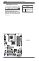
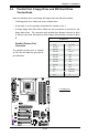
FAN2
FAN3
FAN1
JI2C1
JI2C2
JWOR
FAN4
JP3
JWD
JLED
Battery
DIMM1A
DIMM2A
DIMM1B
DIMM2B
I-SATA4
I-SATA5
WO
Speaker
COM1
KB/MOUSE
CPU Fan
VGA
USB
3/4/5/6
USB 1/2
LAN
Fan5
Audio
4-Pin PWR
Processor
Slot7 PCI-E x1
Slot6 PCI-E x16
Slot5 PCI-E x4
Slot4 PCI-33MHz
JP5
Slot3 PCI-33MHz
JP2
Slot2 PCI-33MHz
Buzzer
SPKR1
Slot1 PCI-33MHz
C2SBA
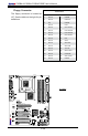
WOL
IDE#2
IDE#1
FP USB 7/8
FP USB 9/10
I-SATA0
I-SATA1
JL1
LE1
Front Panel CTRL
Intel G33
North Bridge
South Bridge
Intel ICH9(R)
24-pin ATX PWR
Audio CTRL
CD-IN
COM2
Front Audio
W83627DHG
Floppy
S I/O
IDE CTRL
ITE 8212
Audio Enabled
Front-Access USB 11Front-Access USB 12
I-SATA2
I-SATA3
JPUSB1
JKB
JPUSB2
GLAN CTRL
JPL1
JBT1
BIOS
Parallel Port
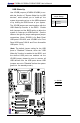
2-7 Jumper Settings
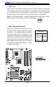
Explanation of
Jumpers
To mo dify the ope rati on of th e
motherboard, jumpers can be used
to choose between optional settings.
Jumpers create shorts between two
pins to change the function of the
connector. Pin 1 is identied with a
square solder pad on the printed circuit
board. See the motherboard layout
pages for jumper locations.
Note: On two pin jumpers, "Closed"
means the jumper is on and "Open"
means the jumper is off the pins.
Connector
Pins
Jumper
Cap
Setting
Pin 1-2 short
3 2 1
3 2 1
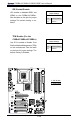
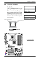
GLAN Enable/Disable
JPL1 enables or disables the GLAN
Port on the motherboard. See the
table on the right for jumper settings.
The default setting is enabled.
GLAN Enable
Jumper Settings
Pin# Denition
1-2 Enabled (default)
2-3 Disabled
A
A. GLAN Port1 Enable