
User's Manual

SBI-7226T-T2 Blade Module User’s Manual
6-6
Super IO Configuration
The menu options in the SUPER IO CONFIGURATION submenu and their descriptions are
shown in Table 6-4.
Chipset Configuration
The CHIPSET CONFIGURATION submenu contains two submenus as shown in Table 6-5.
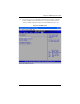
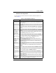
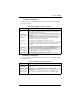
Table 6-4. Super IO Configuration Submenu
Menu Option Description
Serial Port1 Address
This option specifies the base I/O port address and Interrupt Request address of
serial port 1. The options are D
ISABLED, 3F8/IRQ4, 3E8/IRQ4 and 2E8/IRQ3.
• Select D
ISABLED to prevent the serial port from accessing any system
resources. When this option is set to D
ISABLED, the serial port physically
becomes unavailable.
• Select 3F8/IRQ4 to allow the serial port to use 3F8 as its I/O port address
and IRQ 4 for the interrupt address.
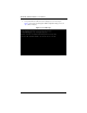
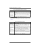
Serial Port2 Address
This option specifies the base I/O port address and Interrupt Request address of
serial port 2. The options are D
ISABLED, 2F8/IRQ3, 3E8/IRQ4 and 2E8/IRQ3.
Select D
ISABLED to prevent the serial port from accessing any system resources.
When this option is set to D
ISABLED, the serial port physically becomes
unavailable.
Select 2F8/IRQ3 to allow the serial port to use 2F8 as its I/O port address and
IRQ 3 for the interrupt address.
Serial Port 2
Mode
This tells the BIOS which mode to select for serial port 2. The options are
Normal, I
RDA and ASKIR.
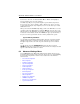
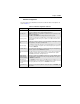
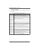
Table 6-5. Chipset Configuration Submenu
Menu Option Description
CPU Bridge
Configuration
This menu configures the CPU Bridge features. For details see Table 6-6.
NorthBridge
Configuration
This menu configures the NorthBridge Chip. For details see Table 6-7.
SouthBridge/
Configuration
This menu configures the SouthBridge Chip. For details see Table 6-8.