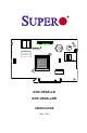
C A C C A A C C C C A A A C C C C C CC CC C C A A A A A A A A A C C 9 10 A A A PCB EDGE 6 PCB EDGE BAR CODE WWN 4 5 7 8 11 12 13 14 15 16 17 18 19 20 21 22 23 24 25 26 PCB EDGE 3 1 3 1 4 1 2 A B C D E F G H J K L M N P R T U V W Y AA AB AC AD AE AF AOC-USAS-L4i AOC-USAS-L4iR USER'S GUIDE Rev. 1.
Add-on Card User's Guide The information in this User’s Manual has been carefully reviewed and is believed to be accurate. The vendor assumes no responsibility for any inaccuracies that may be contained in this document, makes no commitment to update or to keep current the information in this manual, or to notify any person or organization of the updates. Please Note: For the most up-to-date version of this manual, please see our web site at www.supermicro.com.
Safety Information and Technical Specifications Table of Contents Introduction Overview ........................................................................................................... vii Product Features............................................................................................... vii Operating Systems Supported .......................................................................... vii An Important Note to Users ..............................................................
Add-on Card User's Guide 3-11 Clearing a Storage Configuration..................................................................... 3-16 Chapter 4 MegaRAID Storage Manager SoftwareOverview and Installation 4-1 Overview .............................................................................................................. 4-1 Creating Storage Configurations ..................................................................... 4-1 Monitoring Storage Devices ..............................................
Safety Information and Technical Specifications 6-8 Adding a Saved Storage Configuration .............................................................
Add-on Card User's Guide Notes vi
Safety Information and Technical Specifications Introduction Overview This manual is written for system integrators, PC technicians and knowledgeable PC users who intend to integrate SuperMicro's AOC-USAS-L4i and/or the AOCUSAS-L4iR add-on cards to their system. Product Features The AOC-USAS-L4i and the AOC-USAS-L4iR add-on cards offer the following features: • UIO Form Factor. • Internal and External "ipass" cable ports. • Multiple LED Activity/Failure indicators.
Add-on Card User's Guide Contacting SuperMicro Headquarters Address: SuperMicro Computer, Inc. 980 Rock Ave. San Jose, CA 95131 U.S.A. Tel: +1 (408) 503-8000 Fax: +1 (408) 503-8008 Email: marketing@supermicro.com (General Information) support@supermicro.com (Technical Support) Web Site: www.supermicro.com Europe Address: SuperMicro Computer B.V. Het Sterrenbeeld 28, 5215 ML 's-Hertogenbosch, The Netherlands Tel: +31 (0) 73-6400390 Fax: +31 (0) 73-6416525 Email: sales@supermicro.
Safety Information and Technical Specifications Chapter 1 Safety Guidelines To avoid personal injury and property damage, carefully follow all the safety steps listed below when accessing your system or handling the components. 1-1 ESD Safety Guidelines Electric Static Discharge (ESD) can damage electronic components. To prevent damage to your system, it is important to handle it very carefully. The following measures are generally sufficient to protect your equipment from ESD.
Add-on Card User's Guide Notes 1-2
Safety Information and Technical Specifications Chapter 2 LED Indicators and Connectors 2-1 Front Connectors and Jumpers A A A C C C C C C A C A C A C C C C A A A A CC C A C CC 9 10 A C 6 A A C A A A PCB EDGE 1 Buzzer A 2 PCB EDGE BAR CODE WWN 1 4 5 7 8 11 12 13 14 15 16 17 18 19 20 21 22 23 24 26 PCB EDGE 25 3 3 3 1 4 1 2 A B C D E F G H J K L M N P R T U V W Y AA AB AC AD AE AF 4 Front Connectors #1. Internal SAS Connector #2.
Add-on Card User's Guide 2-2 Front Connector and Pin Definitions #1. Internal SAS Connector The Internal SAS port (J3) connects to the backplane allowing the motherboard to access the hard drives and RAID capabilities. This connector supports up to 4 HDD ports. Use a single port SAS "ipass" cable (Super Micro order number CBL - 0108L-02). #2. iButton Socket The iButton is used to enable RAID 5 with the AOC-USAS-L4iR card only.. To do this, you must install a SuperMicro ibutton and enable the SWR5 jumper.
Safety Information and Technical Specifications A A A A C C C C C A A C A C C C C C CC A A A A A C CC C A C 9 10 A A C A A A PCB EDGE 6 C 2-3 Front Jumper Locations and Pin Definitions PCB EDGE BAR CODE WWN 1 2 3 4 5 7 8 11 12 13 14 15 16 17 18 19 20 21 22 23 24 25 26 PCB EDGE 3 1 1 4 A B C D E F G H J K L M N P R T U V W Y AA AB AC AD AE AF SWR5 Explanation of Jumpers To modify the operation of the backplane, jumpers can be used to choose b
Add-on Card User's Guide LED INDICATORS POWER LEDS A A A A C C C C C C A C C A CC C A A A CC A A C C A C C A C A A A0 - A7 A A LNP0 - LNP7 A C C C C C C BAR CODE WWN 3 5 4 5 6 7 8 9 10 11 12 13 14 16 9 10 15 17 18 19 20 11 21 22 12 23 24 25 26 13 14 15 16 17 18 19 20 21 22 23 24 25 26 A 1 2 A 4 3 1 A B C D E F G H J K L M N P R T U V W Y AA AB AC AD AE AF 1 3 PCB EDGE 4 3 PCB EDGE 1 2 A B C D E F G H J K L M N P R
Safety Information and Technical Specifications RAID Minimum Drive Requirements Use the following chart to determine the minimum number of hard drives needed to set up a RAID environment. RAID Minimum Hard Drives RAID 0 2 RAID 1 2 RAID 5* 3* RAID 10 4 (2 RAID 1 Arrays) * Raid 5 is supported by the AOC-USAS-L4iR add-on card.
Add-on Card User's Guide Notes 2-6
Safety Information and Technical Specifications Chapter 3 Driver Installation The MegaRAID BIOS Configuration Utility (CU) is used to configure disk arrays and logical drives and to do other configuration tasks in a pre-bootenvironment. 3-1 Performing a Quick Configuration This section provides high level instructions for quickly configuring arrays and logical drives with the MegaRAID BIOS CU. These instructions are intended for users that are familiar with configuration utilities and tools.
Add-on Card User's Guide 3-2 Configuring Arrays and Logic Drives This section provides detailed instructions for configuring arrays and logical drives with the MegaRAID BIOS CU. LSI recommends that you use drives with the same capacity when you create a storage configuration. If you use drives with different capacities in one array, the CU limits each drive to the capacity of the smallest drive.
Safety Information and Technical Specifications Note: When you start the MegaRAID BIOS CU by pressing Ctrl-H the Configuration Manager Module of the BIOS allocates three segments of memory using either PMM or conventional memory: these are the Destination Segment, Scratch Segment, and Read Write Buffer Segment.
Add-on Card User's Guide Figure 3-2: Logical Drive Configuration 8. Highlight RAID and press Enter. The available RAID levels for the current logical drive are displayed. 9. Select a RAID level for the logical drive and press Enter. 10. (Optional) Change the drive’s default Write Cache and Read Ahead policies (see Section 3-3, “Setting the Hard Disk Write Cache and Read Ahead Policies”). 11. When you have finished defining the current logical drive, select Accept and press Enter. 12.
Safety Information and Technical Specifications Follow these steps to configure a disk array using the New Configuration or View/ Add Configuration option: 1. Select Configuration→ New Configuration or Configuration→ View/Add Configuration from the Management Menu. If you selected New Configuration, select Yes to proceed. (This confirms that you are erasing the existing storage configuration.) The CU displays an array selection window.
Add-on Card User's Guide 9. Select a RAID level for the logical drive and press Enter. 10. (Optional) Set the logical drive size by highlighting Size and Enter. The minimum valid logical drive size is 64 Mbytes. An error will appear if you try to create a logical drive that is smaller 64 Mbytes. By default, all the available space in the array is to the current logical drive. For RAID 10 arrays, only one logical can be defined for the entire array. 11.
Safety Information and Technical Specifications 3. Select an unconfigured drive or Ready drive from the list, and press Enter. 4. When the Physical Drive Property menu appears, select Make Hot Spare and press Enter. 5. Select Yes from the pop-up menu to create the hotspare drive. Note: To remove a hotspare drive, perform steps 1 and 2 above, select the HOTSP disk, press Enter, select Force Offline, and press Enter. The status of the drive changes to READY, and it can then be used in another new array.
Add-on Card User's Guide 5. After the initialization is complete, press Esc to return to previous menus. If you press Esc while initialization is in progress, the following options appear: – Stop: (Available only if AutoResume is enabled on the adapter: Management Menu→ Objects→ Adapter→ AutoResume.) The initialization is stopped, and the CU stores the percentage of the initialization already completed.
Safety Information and Technical Specifications 4. Select Yes at the prompt and press Enter. The CU displays a bar graph showing the initialization progress. 5. When initialization completes, press Esc to return to the previous menu. If you press Esc while initialization is in progress, the Stop, Continue, and Abort options are available, as explained earlier in this section.
Add-on Card User's Guide 3. Use the arrow key to select Off or On for Disk WC (DWC) or Read Ahead. 4. When you see the prompt Change DWC or Change Read Ahead, use the arrow key to select Off or On, then press Enter to change the cache setting. The settings are changed for all logical drives defined on the array. 3-4 Rebuilding a Drive The MegaRAID BIOS CU enables you to rebuild a drive of a redundant array if the array has a failed drive.
Safety Information and Technical Specifications 4. When rebuild is complete, the CU displays the message: Rebuilding of Drive X Completed Successfully. Press Esc. (X = the ID of the rebuilt drive.) 5. Press Esc to display the Management Menu. The state of the rebuilt disk drive changes from FAIL to ONLIN. If you press Esc while the rebuild is running, the following options display: • Stop: (Available only if AutoResume is enabled on the adapter: Management Menu -> Objects -> Adapter -> AutoResume.
Add-on Card User's Guide • CU menus such as Select Boot Drive, Select Adapter, and Logical Drive menus will completely or partially close when a drive is inserted or removed. • If a Rebuild is in progress when you insert or remove a drive, the CU will first display the message Rebuilding Of Drive Not Complete! Press Esc.. followed by the hot plug message.
Safety Information and Technical Specifications 4. Press F10. 5. At the prompt, select Yes to start the Check Consistency process and press Enter. A graph shows the progress of the Check Consistency operation until it is complete. If the MegaRAID BIOS CU finds any data inconsistencies while comparing the source and target drives, it fixes the inconsistency by writing the source data to the target drive.
Add-on Card User's Guide Viewing and Changing Adapter Properties To view or change adapter properties, follow these steps: 1. On the Management Menu, select Objects→ Adapter. 2. Select an adapter from the list. The following list of adapter properties appears: 1. The Disk coercion property can be accessed only when no configuration is present for the adapter. Otherwise, an error message will appear. 3. If you want to change the value of a property, highlight it and press Enter. 4.
Safety Information and Technical Specifications Viewing and Changing Logical Drive Properties To view or change logical drive properties, follow these steps: 1. On the Management Menu, select Objects → Logical Drive. 2. Select View/Update Parameters. The only logical drive properties you can change are Disk WC (Disk Write Cache) and Read Ahead (see Section 3-3, “Setting the Hard Disk Write Cache and Read Ahead Policies”). The other properties are view-only.
Add-on Card User's Guide 3-9 Configuring a Bootable Logical Drive The default boot logical drive is LD 0. If you change the boot drive to another logical drive, the BIOS and the CU will preserve this change. However, if you delete the new boot logical drive, you must be sure to configure another logical drive for booting. The MegaRAID BIOS CU will not automatically select a different boot logical drive. Follow these steps to configure a bootable logical drive: 1.
Safety Information and Technical Specifications Chapter 4 MegaRAID Storage Manager Software Overview and Installation MegaRAID Storage Manager software is a configuration and monitoring utility used with the Embedded MegaRAID Software. This chapter provides a brief overview of the MegaRAID Storage Manager software and explains how to install it on the supported operating systems.
Add-on Card User's Guide You can use the Configuration Wizard Auto Configuration mode to automatically create the best possible configuration with the available hardware. You can use the Guided Configuration mode, which asks you a few brief questions about the configuration, and then creates it for you. Or you can use the Manual Configuration mode, which gives you complete control over all aspects of the storage configuration.
Safety Information and Technical Specifications 4-3 Installation This section explains how to install (or reinstall) MegaRAID Storage Manager software on your workstation or server for the supported operating systems: Microsoft Windows, Red Hat Linux, and SUSE Linux. 5.3.
Add-on Card User's Guide Figure 4.1: Customer Information Screen 4. Enter your user name and organization name. In the bottom part of the screen, select an installation option: – If you select All users, any user with administrative privileges can use this version of MegaRAID Storage Manager software to view or change storage configurations. – If you select Only for current user, the MegaRAID Storage Manager shortcuts and associated icons will be available only to the user with this user name. 5.
Safety Information and Technical Specifications Figure 4.2: Customer Information Screen 7. Select one of the Setup options. The options are fully explained in the screen text. – Normally, you would select Complete if you are installing MegaRAID Storage Manager software on a server. – Select Client if you are installing MegaRAID Storage Manager software on a PC that will be used to view and configure servers over a network.
Add-on Card User's Guide If you select Client installation for a PC used to monitor servers, and if there are no available servers with a registered framework on the local subnet (that is, servers with a complete installation of MegaRAID Storage Manager software), you cannot connect to a remote server unless you first edit the startupui.bat file. Specifically, you must add the IP address of the remote server to the end of the startupui.bat file. For example, to connect to a remote framework on server 192.168.0.
Safety Information and Technical Specifications Linux Error Messages One or more of the following messages may appear while you are installing MegaRAID Storage Manager software on a Linux system: • More than one copy of MegaRAID Storage Manager software has been installed. This message indicates that the user has installed more than one copy of MegaRAID Storage Manager software.
Add-on Card User's Guide Notes 4-8
Safety Information and Technical Specifications Chapter 5 MegaRAID Storage Manager Window and Menus This chapter explains how to start MegaRAID Storage Manager software and describes the MegaRAID Storage Manager window and menus. 5-1 Starting MegaRAID Storage Manager Software Follow these steps to start MegaRAID Storage Manager software and view the main window: 1.
Add-on Card User's Guide Figure 5-1: Select Server Window If the circle in the server icon is yellow instead of green, it means that the server is running in a degraded state—for example, because a disk drive used in a virtual disk has failed. If the circle is red, the storage configuration in the server has failed.
Safety Information and Technical Specifications Figure 5-2: Select Server Window 3. Select an access mode from the drop-down menu. – Select Full Access if you need to both view the current configuration and change the configuration. – Select View Only if you need to only view and monitor the configuration. 4. Enter your user name and password, and click Login. Note: If the computer is networked, this is the login to the computer itself, not the network login.
Add-on Card User's Guide 5-2 MegaRAID Storage Manager Window This section describes the MegaRAID Storage Manager window, which is shown in Figure 5-3. The following topics describe the panels and menu options that appear in this window.
Safety Information and Technical Specifications Physical/Logical View Panel The left panel of the MegaRAID Storage Manager window displays either the Physical view or the Logical view of the system and the devices in it, depending on which tab is selected. • The Physical view shows the hierarchy of physical devices in the system. At the top of the hierarchy is the system itself. One or more controllers are installed in the system. Each controller has one or more ports.
Add-on Card User's Guide Properties/Operations/Graphical View Panel The right panel of the MegaRAID Storage Manager window has either two or three tabs, depending on what kind of device is selected in the left panel. • The Properties tab displays information about the selected device. For example, if a controller icon is selected in the left panel, the Properties tab lists information such as the controller name and the device port count.
Safety Information and Technical Specifications Menu Bar Here are brief descriptions of the main selections on the MegaRAID Storage Manager menu bar. File Menu The File menu has an Exit option for exiting from the MegaRAID Storage Manager software. It also has a Rescan option for updating the display in the MegaRAID Storage Manager window. (Rescan is seldom required; the display normally updates automatically.
Add-on Card User's Guide Log Menu The Log menu includes options for saving and clearing the message log. Help Menu On the Help menu you can select Help -> Help to view the MegaRAID Storage Manager software online help file. You can select Help -> About to view version information for the MegaRAID Storage Manager software. Note: When you use the MegaRAID Storage Manager software online help, you may see a warning message that Internet Explorer has restricted the file from showing active content.
Safety Information and Technical Specifications Chapter 6 Configuration You use MegaRAID Storage Manager software to create and modify storage configurations. RAID 0, RAID 1, RAID 5, and RAID 10 storage configurations are supported. Important: LSI recommends that you do not use both SAS and SATA drives in the same array. Using different drive interfaces in this way could cause unpredictable behavior, decreased performance, an increased error count, and decreased MTBF.
Add-on Card User's Guide Figure 6-1: First Screen Configuration Wizard The menu lists three configuration modes: • Auto Configuration automatically creates an optimal configuration from the available disk drives. • Manual Configuration gives you the greatest level of control in creating a new virtual disk. • Guided Configuration asks you a few simple questions about what kind of configuration you want and then automatically creates it from the available disk drives.
Safety Information and Technical Specifications The following subsections explain how to use the Configuration Wizard to create storage configurations: • “Understanding Virtual Disk Parameters” • “Using Auto Configuration” • “Using Guided Configuration” • “Using Manual Configuration: RAID 0” • “Using Manual Configuration: RAID 1” • “Using Manual Configuration: RAID 5” • “Using Manual Configuration: RAID 10” Understanding Virtual Disk Parameters This section describes the Virtual Disk Parameters that you can set whe
Add-on Card User's Guide Using Auto Configuration Auto Configuration is the quickest and simplest way to create a new storage configuration. When you select Auto Configuration mode on the first Configuration Wizard screen, the Configuration Wizard creates the best configuration possible using the available physical disks. Figure 7-2: Auto Configuration Screen Follow these steps to create a new storage configuration in Auto Configuration mode: 1.
Safety Information and Technical Specifications 2. Select an initialization option from the drop-down menu at the bottom of the window: – No Initialization: The new configuration is not initialized, and the existing data on the disks is not overwritten. – Fast Initialization: MegaRAID Storage Manager software quickly writes zeroes to the first and last 8 Mbyte regions of the new virtual disk. – Full Initialization: A complete initialization is done on the new configuration.
Add-on Card User's Guide Figure 6-3: First Guided Conguration Screen Follow these steps to create a new storage configuration in Guided Configuration mode: 1. Select a redundancy option at the top of the Guided Configuration window: – Redundancy Only: Create a configuration only if redundancy (RAID 1) is possible. – Redundancy when possible: Create a redundant configuration if possible. Otherwise, create a non-redundant configuration. – No Redundancy: Create a non-redundant configuration. 2.
Safety Information and Technical Specifications 3. Select a maximum number of virtual disks to be created. The Configuration Wizard may not be able to create as many virtual disks as you want, depending on the current configuration and the number of virtual disks that have already been created. 4. Click Next to continue to the next window, as shown in Figure 6.4. Figure 6-4: Second Guided Configuration Screen 5. Change the default volume parameters in this window, if needed.
Add-on Card User's Guide Using Manual Configuration: RAID 0 Follow these steps to create a RAID 0 storage configuration using the Manual Configuration mode of the Configuration Wizard. Figure 6-5 shows the first screen that appears when you select Manual Configuration. Figure 6-5: Manual Configuration - First Manual Configuration Screen 1. In the first Manual Configuration window, select two or more available drives in the left panel. Click the Right Arrow button to move the selected drives to the right panel.
Safety Information and Technical Specifications Figure 6-6: Manual Configuration - Defining a Virtual Disk The Arrays with Free Space menu lists the new array that you just defined, plus any existing arrays with holes (free space) that could be used for a new configuration. 4. From the Arrays with Free Space menu, select the array to use for the new virtual disk. 5. In the right panel, select RAID 0 as the RAID level. 6.
Add-on Card User's Guide Using Manual Configuration: RAID 1 Follow these steps to create a RAID 1 storage configuration using the Manual Configuration mode of the Configuration Wizard: 1. In the first Manual Configuration window, shown in Figure 6-5, select two available drives in the left panel. Click the Right Arrow button to move the selected drives to the right panel.
Safety Information and Technical Specifications 4. To remove a hotspare from an array, select it in the right panel and click Remove HotSpare. 5. Click Next. The next Configuration Wizard window appears, as shown in Figure 6.6. The Arrays with Free Space menu lists the new array(s) that you just defined, plus any existing arrays with holes (free space) that could be used for a new configuration. 6. Select the array to use for the new virtual disk. 7. In the right panel, select RAID 1 as the RAID level. 8.
Add-on Card User's Guide Using Manual Configuration: RAID 5 Follow these steps to create a RAID 5 storage configuration using the Manual Configuration mode of the Configuration Wizard. Remember that RAID 5 requires: • AOC-USAS-L4iR card with the enabled SWR5 jumper enabled • activated Super Micro iButton • minimum of three hard drives In the first Manual Configuration window, select three available drives in the left panel. Click the Right Arrow button to move the selected drives to the right panel.
Safety Information and Technical Specifications 9. Click Next to continue with the next configuration step. The Virtual Disk Summary window appears. 10. Review the configuration shown in the Virtual Disk Summary window. If you want to change something, click Back and change the configuration parameters. 11. Click Finish to accept the configuration and start the initialization process (unless you selected No Initialization earlier).
Add-on Card User's Guide 10. Click Accept to accept the configuration of the new virtual disk. Note: Click the Reclaim button if you want to undo a virtual disk that you just defined. 11. Click Next to continue with the next configuration step. The Virtual Disk Summary window appears. 12. Review the configuration shown in the window. If you want to change something, click Back and change the configuration parameters. 13.
Safety Information and Technical Specifications 6-3 Changing Adjustable Task Rates Follow these steps if you need to change the adjustable rates for rebuilds and other system tasks that run in the background: Note: LSI recommends that you leave the adjustable task rates at their default settings to achieve the best system performance. If you raise the task rates above the defaults, foreground tasks will run more slowly and it may seem that the system is not responding.
Add-on Card User's Guide 6-4 Changing Virtual Disk Properties You can change a virtual disk’s Read Policy, Write Policy, and other properties at any time after the virtual disk is created. To do this, follow these steps: 1. Select a virtual disk icon in the left panel of the MegaRAID Storage Manager window. 2. In the right panel, select the Properties tab, and then select Set Virtual Disk Properties. A list of Virtual Disk Properties appears in the right panel. 3.
Safety Information and Technical Specifications 6-6 Saving a Storage Configuration to Disk You can save an existing controller configuration to a file so you can apply it to another controller. To save a configuration file, follow these steps: 1. Select a controller icon in the left panel of the MegaRAID Storage Manager window. 2. On the menu bar, select Operations -> Advanced Operations -> Configuration -> Save Configuration. The Save dialog box appears. 3.
Add-on Card User's Guide 6-8 Adding a Saved Storage Configuration When you replace a controller, or when you want to duplicate an existing storage configuration on a new controller, you can add a saved configuration to the controller. Caution: When you add a saved configuration to a replacement controller, be sure that the number and size of the physical disks connected to the controller are exactly the same as when the configuration was saved. To add a saved configuration, follow these steps: 1.