SUPER ® SUPERSERVER 6113L-8 SUPERSERVER 6113L-i USER’S MANUAL 1.
The information in this User’s Manual has been carefully reviewed and is believed to be accurate. The vendor assumes no responsibility for any inaccuracies that may be contained in this document, makes no commitment to update or to keep current the information in this manual, or to notify any person or organization of the updates. Please Note: For the most up-to-date version of this manual, please see our web site at www.supermicro.com.
Preface Preface About This Manual This manual is written for professional system integrators and PC technicians. It provides information for the installation and use of the SuperServer 6113L-8/ 6113L-i. Installation and maintainance should be performed by experienced technicians only. The SuperServer 6113L-8/6113L-i is a high-end, dual Itanium2 processor rackmount server based on the SC813HS-500/SC813Hi-500 1U rackmount server chassis and the i2DML-8G2/i2DML-iG2 serverboard.
SUPERSERVER 6113L-8/6113L-i User's Manual Chapter 5: Advanced Serverboard Setup Chapter 5 provides detailed information on the i2DML-8G2/i2DML-iG2 serverboard, including the locations and functions of connectors, headers and jumpers. Refer to this chapter when adding or removing processors or main memory and when reconfiguring the serverboard. Chapter 6: Advanced Chassis Setup Refer to Chapter 6 for detailed information on the 1U SC813HS-500/SC813Hi-500 rackmount server chassis.
Preface Notes v
SUPERSERVER 6113L-8/6113L-i User's Manual Table of Contents Preface About This Manual ....................................................................................................... iii Manual Organization .................................................................................................... iii Chapter 1: Introduction 1-1 Overview ............................................................................................................ 1-1 1-2 Serverboard Features .............
Table of Contents Chapter 4: System Safety 4-1 Electrical Safety Precautions ........................................................................... 4-1 4-2 General Safety Precautions ............................................................................. 4-2 4-3 ESD Precautions ............................................................................................... 4-3 4-4 Operating Precautions ......................................................................................
SUPERSERVER 6113L-8/6113L-i User's Manual SMB ......................................................................................................... 5-21 SMB Power Connector ........................................................................... 5-21 5-9 Jumper Settings ............................................................................................. 5-22 Explanation of Jumpers .......................................................................... 5-22 CMOS Clear ....................
Table of Contents Appendices: Appendix A: BIOS Error Beep Codes ...................................................................... A-1 Appendix B: BIOS POST Codes .............................................................................. B-1 Appendix C: Software Installation ............................................................................ C-1 Appendix D: System Specifications ........................................................................
SUPERSERVER 6113L-8/6113L-i User's Manual Notes x
Chapter 1: Introduction Chapter 1 Introduction 1-1 Overview The Supermicro SuperServer 6113L-8/6113L-i is a high-end dual processor, 1U rackmount server that features some of the most advanced technology currently available. The SuperServer 6113L-8/6113L-i is comprised of two main subsystems: the SC813HS-500/SC813Hi-500 1U rackmount chassis and the i2DML8G2/i2DML-iG2 dual Itanium2 processor serverboard.
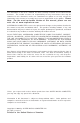
SUPERSERVER 6113L-8/6113L-i User's Manual Note: "(B)" indicates black. 1-2 Serverboard Features At the heart of the SuperServer 6113L-8/6113L-i lies the i2DML-8G2/i2DML-iG2, a dual Intel Itanium2 processor serverboard designed to provide maximum performance. Below are the main features of the i2DML-8G2/i2DML-iG2. Chipset The i2DML-8G2/i2DML-iG2 is based on Intel's E8870 chipset, which is a highperformance chipset designed for high-end server platforms (see Figure 1-1).
Chapter 1: Introduction Processors The i2DML-8G2/i2DML-iG2 supports single or dual Intel Itanium2 processors of up to 1.50 GHz with a 6 MB L3 cache at a 400 MHz FSB. Please refer to the support section of our web site for a complete listing of supported processors (http://www.supermicro.com/support/). Memory The i2DML-8G2/i2DML-iG2 has eight 184-pin, DIMM slots that can support up to 16 GB of low-profile, registered ECC DDR200 (PC1600) SDRAM (DDR266 is supported but at 200 MHz only).
SUPERSERVER 6113L-8/6113L-i User's Manual Other Features Other onboard features are included to promote system health. These include various voltage monitors, two CPU temperature sensors, four fan speed sensors, a chassis intrusion header, auto-switching voltage regulators, chassis and CPU overheat sensors, virus protection and BIOS rescue. Figure 1-1. E8870 Chipset Block Diagram Processor 1 Processor 2 16 GB (Max.
Chapter 1: Introduction 1-3 Server Chassis Features The SC813HS-500/SC813Hi-500 is one of Supermicro's third-generation 1U chassis and features four SCSI/IDE hard drive bays, a slim CD-ROM drive and a revolutionary cooling design that can keep today's most powerful processors running well below their temperature thresholds. The following is a general outline of the main features of the SC813HS/SC813Hi-500 chassis.
SUPERSERVER 6113L-8/6113L-i User's Manual Cooling System The SC813HS-500/SC813Hi-500 chassis' revolutionary cooling design has been optimized to provide sufficient cooling for dual Itanium2 configurations. The SC813HS-500/SC813Hi-500 includes two heavy duty 10-cm blower fans located in the middle of the chassis. These fans operate continuously at full rpm. If they break down, the ambient air temperature inside the chassis will rise and activate an overheat LED.
Chapter 1: Introduction 1-4 Contacting Supermicro Headquarters Address: Tel: Fax: Email: Web Site: SuperMicro Computer, Inc. 980 Rock Ave. San Jose, CA 95131 U.S.A. +1 (408) 503-8000 +1 (408) 503-8008 marketing@supermicro.com (General Information) support@supermicro.com (Technical Support) www.supermicro.com Europe Address: Tel: Fax: Email: SuperMicro Computer B.V. Het Sterrenbeeld 28, 5215 ML 's-Hertogenbosch, The Netherlands +31 (0) 73-6400390 +31 (0) 73-6416525 sales@supermicro.
SUPERSERVER 6113L-8/6113L-i User's Manual Notes 1-8
Chapter 2: Server Installation Chapter 2 Server Installation 2-1 Overview This chapter provides a quick setup checklist to get your SuperServer 6113L-8/ 6113L-i up and running. Following these steps in the order given should enable you to have the system operational within a minimum amount of time. This quick setup assumes that your SuperServer 6113L-8/6113L-i system has come to you with the processors and memory preinstalled.
SUPERSERVER 6113L-8/6113L-i User's Manual Choosing a Setup Location - Leave enough clearance in front of the rack to enable you to open the front door completely (~25 inches). - Leave approximately 30 inches of clearance in the back of the rack to allow for sufficient airflow and ease in servicing. ! Warnings and Precautions! ! Rack Precautions - Ensure that the leveling jacks on the bottom of the rack are fully extended to the floor with the full weight of the rack resting on them.
Chapter 2: Server Installation 2-4 Installing the Server into a Rack This section provides information on installing the SuperServer 6113L-8/6113L-i into a rack unit with the rack rails provided. If the 6113L-8/6113L-i has already been mounted into a rack, you can skip ahead to Sections 2-5 and 2-6. There are a variety of rack units on the market, which may mean the assembly procedure will differ slightly. You should also refer to the installation instructions that came with the rack unit you are using.
SUPERSERVER 6113L-8/6113L-i User's Manual Figure 2-1. Installing the Rack Rails Installing the Server into the Rack You should now have rails attached to both the chassis and the rack unit. The next step is to install the server into the rack. Do this by lining up the rear of the chassis rails with the front of the rack rails. Slide the chassis rails into the rack rails, keeping the pressure even on both sides (you may have to depress the locking tabs when inserting). See Figure 2-2.
Chapter 2: Server Installation Figure 2-2.
SUPERSERVER 6113L-8/6113L-i User's Manual Installing the Server into a Telco Rack If you are installing the SuperServer 6113L-86113L-8/6113L-i into a Telco type rack, follow the directions given on the previous pages for rack installation. The only difference in the installation procedure will be the positioning of the rack brackets to the rack. They should be spaced apart just enough to accommodate the width of the telco rack. Figure 2-3.
Chapter 2: Server Installation 2-5 Checking the Serverboard Setup After you install the 6113L-8/6113L-i in the rack, you will need to open the unit to make sure the serverboard is properly installed and all the connections have been made. 1. Accessing the inside of the 6113L-8/6113L-i (see Figure 2-4): First, release the retention screws that secure the unit to the rack. Grasp the two handles on either side and pull the unit straight out until it locks (you will hear a "click").
SUPERSERVER 6113L-8/6113L-i User's Manual Figure 2-4. Accessing the Inside of the SuperServer 6113L-8/6113L-i 6. Check all cable connections and airflow: Make sure all power and data cables are properly connected and not blocking the chassis airflow. See Chapter 5 for details on cable connections. Also, check the air seals for damage. The air seals are located under the blower fan and beneath the frame cross section that separates the drive bay area from the serverboard area of the chassis.
Chapter 2: Server Installation 2-6 Checking the Drive Bay Setup Next, you should check to make sure the peripheral drives and the SCSI/IDE drives have been properly installed and all connections have been made. 1. Accessing the drive bays: All drives are accessable from the front of the server. For servicing the CDROM and IDE drives, you will need to remove the top chassis cover (not necessary for SCSI drives). See Chapter 6 for details. 2.
SUPERSERVER 6113L-8/6113L-i User's Manual Notes 2-10
Chapter 3: System Interface Chapter 3 System Interface 3-1 Overview There are several LEDs on the chassis control panel to keep you constantly informed of the overall status of the system as well as the activity and health of specific components. There are also two buttons on the chassis control panel and an on/off switch on the power supply. This chapter explains the meanings of all LED indicators and the appropriate response you may need to take.
SUPERSERVER 6113L-8/6113L-i User's Manual 3-3 Control Panel LEDs The control panel located on the front of th SC813HS-500/SC813Hi-500 chassis has four LEDs. These LEDs provide you with critical information related to different parts of the system. This section explains what each LED indicates when illuminated and any corrective action you may need to take. ! OVERHEAT: Indicates an overheat condition in the chassis.
Chapter 3: System Interface ! Power: Indicates power is being supplied to the system's power supply units. This LED should normally be illuminated when the system is operating. 3-4 SCSI Drive Carrier LEDs (6113L-8 only) Each SCSI drive carrier has two LEDs. ! Green: When illuminated, the green LED on the front of the SCSI drive carrier indicates drive activity. A connection to the SCSI SCA backplane enables this LED to blink on and off when that particular drive is being accessed.
SUPERSERVER 6113L-8/6113L-i User's Manual Notes 3-4
Chapter 4: System Safety Chapter 4 System Safety 4-1 Electrical Safety Precautions ! Basic electrical safety precautions should be followed to protect yourself from harm and the SuperServer 6113L-8/6113L-i from damage: ! Be aware of the locations of the power on/off switch on the chassis as well as the room's emergency power-off switch, disconnection switch or electrical outlet. If an electrical accident occurs, you can then quickly remove power from the system.
SUPERSERVER 6113L-8/6113L-i User's Manual ! The power supply power cord must include a grounding plug and must be plugged into grounded electrical outlets. ! Serverboard Battery: CAUTION - There is a danger of explosion if the onboard battery is installed upside down, which will reverse its polarities. On the i2DML-8G2/i2DML-iG2, the positive side should be facing up. This battery must be replaced only with the same or an equivalent type recommended by the manufacturer.
Chapter 4: System Safety ! After accessing the inside of the system, close the system back up and secure it to the rack unit with the retention screws after ensuring that all connections have been made. 4-3 ESD Precautions ! Electrostatic discharge (ESD) is generated by two objects with different electrical charges coming into contact with each other. An electrical discharge is created to neutralize this difference, which can damage electronic components and printed circuit boards.
SUPERSERVER 6113L-8/6113L-i User's Manual 4-4 Operating Precautions ! Care must be taken to assure that the chassis cover is in place when the 6113L8/6113L-i is operating to ensure proper cooling. Out of warranty damage to the 6113L-8/6113L-i system can occur if this practice is not strictly followed.
Chapter 5: Advanced Serverboard Setup Chapter 5 Advanced Serverboard Setup This chapter covers the steps required to install processors and heatsinks to the i2DML-8G2/i2DML-iG2 serverboard, connect the data and power cables and install add-on cards. All serverboard jumpers and connections are described and a layout and quick reference chart are included in this chapter. Remember to close the chassis completely when you have finished working on the serverboard to protect and cool the system sufficiently.
SUPERSERVER 6113L-8/6113L-i User's Manual 5-2 Itanium2 Processor and Heatsink Installation ! When handling the processor package, avoid placing direct pressure on the label area of the fan. Also, do not place the serverboard on a conductive surface, which can damage the BIOS battery and prevent the system from booting up. IMPORTANT: Always connect the power cord last and always remove it before adding, removing or changing any hardware components.
Chapter 5: Advanced Serverboard Setup Installing the Heatsink Retention Mechanism 1. Place the retention mechanism (SKT-0147-RM-IT2) on the serverboard as shown in the picture below: 2. Secure the retention mechanism to the serverboard by screwing three 6-32, 4.5-mm screws into the mounting holes on the back of the serverboard. Figure 5-1. Installing Heatsink Retention Mechanism 1.) Place the retention mechanism on the serverboard. 2.) Screw in three 6-32 4.
SUPERSERVER 6113L-8/6113L-i User's Manual Installing Itanium2 CPUs 1. Insert an Itanium2 CPU into the CPU1 socket. Make sure that CPU Pin 1 is aligned with the cut angle of the CPU socket, as shown in the picture below.* Itanium2 CPU CPU1 Socket 2. Use the M2.5 hex key to secure the Itanium2 CPU as shown in the picture below. Securing the CPU with an M2.5 hex key 3. Make sure that the CPU is in its properly locked position. To lock it, use the M2.5 hex key to turn the lock in a clockwise direction.
Chapter 5: Advanced Serverboard Setup Installing the Power Pods The CPU power pod is a VRM mechanism specially designed for Itanium2 processors. 1. Locate the slot on the CPU power pod and align it with the Itanium2 CPU installed on the serverboard. 2. Carefully push the edge connector of the power pod toward the CPU until the signal pins on both edges of the CPU are fully seated in the edge connector and you hear a click.
SUPERSERVER 6113L-8/6113L-i User's Manual 3. Locate four of the M3 screws in the heatsink retention package and use them to secure the power pod onto the serverboard as shown in the picture below. Securing the power pod with four M3 screws. 4. Repeat steps 1 and 2 to install a second power pod as needed. Figure 5-2.
Chapter 5: Advanced Serverboard Setup Installing Heatsinks (for CPUs without heatsinks) Warning: Do not apply any thermal grease to the heatsink; the required amount of thermal grease has already been applied. To maximizing the cooling effect of the i2DML-8G2/i2DML-iG2, we strongly recommend that Supermicro's proprietary heatsinks (SNK-0046) be used with Itanium2 CPUs. 1.
SUPERSERVER 6113L-8/6113L-i User's Manual 3. Secure the heatsink onto the CPU by tightening all four screws. 4. Repeat the above steps to install a second heatsink on a second CPU if needed. Figure 5-3. CPUs (2) with Heatsinks Installed Connecting AC Power 1. Connect the 24-pin power connector from the AC power supply to the serverboard. See the serverboard layout diagram in this chapter for the locations of the power connectors. 2.
Chapter 5: Advanced Serverboard Setup 5-3 Connecting Cables Now that the processors are installed, the next step is to connect the cables to the serverboard. These include the data (ribbon) cables for the peripherals and control panel and the power cables. Connecting Data Cables The ribbon cables used to transfer data from the peripheral devices have been carefully routed in preconfigured systems to prevent them from blocking the flow of cooling air that moves through the system from front to back.
SUPERSERVER 6113L-8/6113L-i User's Manual Connecting the Control Panel The U66 header contains pins for various buttons and indicators that are normally located on the chassis control panel. These connectors are designed specifically for use with Supermicro server chassis. All U66 wires have been bundled into single ribbon cable to simplify their connection. The red wire should plug into pin 1 as marked on the serverboard.
Chapter 5: Advanced Serverboard Setup 5-4 I/O Ports The I/O ports are color coded in conformance with the PC 99 specification. See Figure 5-5 below for the locations of the various I/O ports. Figure 5-5. I/O Port Locations COM Port 5-5 USB Ports GLAN1 GLAN2 VGA Port External SCSI (6113L-8 only) Installing Memory Note: Check the Supermicro web site for recommended memory modules: http:// www.supermicro.
SUPERSERVER 6113L-8/6113L-i User's Manual Memory Support The i2DML-8G2/i2DML-iG2 supports up to 16 GB of buffered, reistered ECC DDR200 (DDR266 memory can be used but will operate at DDR200 speed). This serverboard was designed to support 2 GB modules in each socket. You should not mix DIMMs of different sizes and speeds. See Figures 5-6a and 5-6b for installing and removing memory modules. Figure 5-6a.
Chapter 5: Advanced Serverboard Setup 5-6 Adding PCI Cards 1. PCI-X slot: The i2DML-8G2/i2DML-iG2 has one 64-bit 133 MHz PCI-X slot. The server should have come with a riser card installed, which supports a standard sized PCI-X card (see Figure 5-7). 2. PCI card installation: Before installing a PCI add-on card, see step 1, above. Begin by swinging the release tab on the I/O backpanel shield out to the left for the PCI slot.
SUPERSERVER 6113L-8/6113L-i User's Manual 5-7 Serverboard Details Figure 5-8.
Chapter 5: Advanced Serverboard Setup i2DML-8G2/i2DML-iG2 Quick Reference Jumper Description Default Setting CN5 J7 J31 JBT1 JA1* JV1 Power Fail Alarm Enable/Disable GLAN Enable/Disable Watch Dog CMOS Clear SCSI Enable/Disable VGA Enable/Disable Closed (Disabled) Pins 1-2 (Enabled) Pins 1-2 (Reset) See Section 5-9 Pins 1-2 (Enabled) Pins 1-2 (Enabled) Connector Description DS3/DS4 DS7* Fan1 - 8 J1 J2 J3* J5 J6 J9 - J16** J18* J19 J20 J21 J22 J25 J26 J27 J30/J29 J31 J36 J37/J35 J38 S1-6 U62 U66 Deb
SUPERSERVER 6113L-8/6113L-i User's Manual 5-8 Connector Definitions EPS 12V Power Connector There are two 24-pin main power supply connectors on the serverboard. These power connectors meet the SSI EPS 12V specification. See the table on the right for pin definitions. (Only one of the two connections need to be made.) 12V, 24-pin Power Supply Connector Pin Definitions (J20, J36) Pin Number Definition Pin Number Definition 1 +3.3V 13 +3.3V 2 +3.
Chapter 5: Advanced Serverboard Setup HDD LED The HDD LED connection is located on pins 13 and 14 of U66. Attach the hard drive LED cable here to display disk activity for any hard drives on the system. See the table on the right for pin definitions. NIC1 LED HDD LED Pin Definitions (U66) Pin Number Definition 13 Vcc 14 HD Active NIC LED Pin Definitions (U66) The NIC (Network Interface Controller) LED connection for the GLAN port is located on pins 11 and 12 of U66.
SUPERSERVER 6113L-8/6113L-i User's Manual Reset Button Reset Pin Definitions (U66) The Reset Button connection is located on pins 3 and 4 of U66. Attach it the hardware reset switch on the computer case to these pins. Refer to the table on the right for pin definitions. Pin Number Definition 3 Reset 4 Ground Power Button Power Button Connector Pin Definitions (U66) The Power Button connection is located on pins 1 and 2 of U66. Momentarily contacting both pins will power on/off the system.
Chapter 5: Advanced Serverboard Setup Front Panel Universal Serial Bus Header Two extra USB headers (USB2/3 located at J21) can be used to provide front side USB access. You will need a USB cable to use either connection. Refer to the table on the right for pin definitions. Front Panel Universal Serial Bus Pin Definitions (J21) Pin Number 1 2 3 4 5 Definition +5V P0P0+ Ground Key Serial Ports There are two Serial Ports on the serverboard.
SUPERSERVER 6113L-8/6113L-i User's Manual Fan Headers The i2DML-8G2/i2DML-iG2 has eight fan headers, designated Fan1 through Fan8. See the table on the right for pin definitions. Fan Header Pin Definitions (Fan1-Fan8) Pin Number 1 2 3 Definition Ground (black) +12V (red) Tachometer Caution: Fan headers are DC power. Power Fault Connect a cable from your power supply to the U62 header to provide warning of power supply failure.
Chapter 5: Advanced Serverboard Setup SMB SMB Header Pin Definitions (J22) A System Management Bus header is located at J22. Connect the appropriate cable here to utilize SMB on your system. Pin Number 1 2 3 4 Definition Data Ground Clock No Connection SMB Power (I2C ) Connector The I2C connector at J27, located between the PWR ForceOn Header and the PWR Fault header, monitors the status of the power supply, the fans, and the system temperature.
SUPERSERVER 6113L-8/6113L-i User's Manual 5-9 Jumper Settings Explanation of Jumpers Connector Pins To modify the operation of the serverboard, jumpers can be used to choose between optional settings. Jumpers create shorts between two pins to change the function of the connector. Pin 1 is identified with a square solder pad on the printed circuit board. See the serverboard layout page for jumper locations.
Chapter 5: Advanced Serverboard Setup GLAN Enable/Disable Change the setting of jumper J7 to enable or disable the onboard GLAN ports (GLAN1 and GLAN2) on the serverboard. See the table on the right for jumper settings. The default setting is enabled GLAN Enable/Disable Jumper Settings (J7) Jumper Position Pins 1-2 Pins 2-3 Definition Enabled Disabled Watch Dog Enable/Disable J31 controls Watch Dog, a system monitor that takes action when a software application freezes the system.
SUPERSERVER 6113L-8/6113L-i User's Manual SCSI Enable/Disable (6113L-8 only) The SCSI jumper at JA1 allows you to enable or disable the onboard SCSI controller. The normal (default) position is on pins 1-2 to enable SCSI termination. See the table on the right for jumper settings.
Chapter 5: Advanced Serverboard Setup SCSI Activity LED (6113L-8 only) The SCSI Activity LED is located next to the LSI SCSI controller. When the SCSI Activity LED blinks, it indicates that one or both of the SCSI channels are active. 5-11 SCSI and IDE Disk Drive Connections When connecting the hard disk drive cables, please note that a red mark on a wire typically designates the location of pin 1. IDE Connectors There are no jumpers to configure the onboard IDE#1 and #2 connectors.
SUPERSERVER 6113L-8/6113L-i User's Manual Ultra320 SCSI Connectors (6113L-8 only) Refer to the table below for the pin definitions of the Ultra320 SCSI connectors at J18 (SCSI channel A and J3 (SCSI channel B).
Chapter 6: Advanced Chassis Setup Chapter 6 Advanced Chassis Setup This chapter covers the steps required to install components and perform maintenance on the SC813HS-500/SC813Hi-500 chassis. For component installation, follow the steps in the order given to eliminate the most common problems encountered. If some steps are unnecessary, skip ahead to the next step. Tools Required The only tool you will need to install components and perform maintenance is a Philips screwdriver.
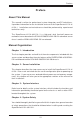
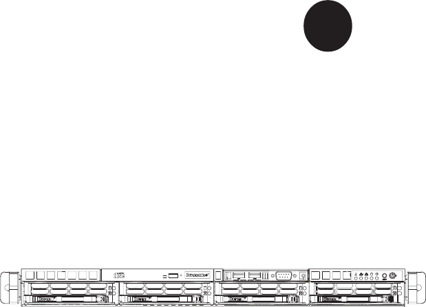
SUPERSERVER 6113L-8/6113L-i User's Manual CD-ROM Drive USB Ports COM Port SCSI/IDE Drives Control Panel/System LEDs System Reset VGA Port COM1 Port USB Ports Ethernet Ports Main Power PCI-X Slot External SCSI Port (6113L-8 only) Figure 6-1. Chassis: Front and Rear Views 6-2 Control Panel The control panel (located on the front of the chassis) must be connected to the JF2 connector on the serverboard to provide you with system status indications.
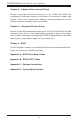
Chapter 6: Advanced Chassis Setup 6-3 System Fans Two 10-cm blower fans and a high-speed 4-cm fan provide all the cooling needed for the SuperServer 6113L-8/6113L-i. It is very important that the chassis top cover is properly installed and making a good seal for the cooling air to circulate properly through the chassis and cool the components. See Figure 6-2. System Fan Failure If a fan fails, the ambient air temperature in the chassis will rise and activate the overheat LED on the control panel.
SUPERSERVER 6113L-8/6113L-i User's Manual 10-cm Blower Fans 4-cm Cooling Fan Figure 6-2. System Cooling Fans 6-4 Drive Bay Installation/Removal Removing the Front Bezel If your system has a front bezel (optional) attached to the chassis, you must first remove it to gain access to the drive bays. To remove the bezel, first unlock the front of the chassis then press the release knob (see Figure 6-3). Carefully remove the bezel with both hands.
Chapter 6: Advanced Chassis Setup Figure 6-3. Removing the Front Bezel 1. Unlock 2. Press release knob 3. Remove bezel assembly Accessing the Drive Bays SCSI/IDE Drives: Because of their hotswap capability, you do not need to access the inside of the chassis or power down the system to install or replace SCSI drives. Proceed to the next step for instructions. (For installing/removing IDE drives, you do not need to access the inside of the system but you will need to remove power from the system first.
SUPERSERVER 6113L-8/6113L-i User's Manual SCSI/IDE Drive Installation 1. Mounting a SCSI/IDE drive in a drive carrier: The SCSI/IDE drives are mounted in drive carriers to simplify their installation and removal from the chassis. These carriers also help promote proper airflow for the SCSI/IDE drive bays. For this reason, even empty carriers without SCSI/IDE drives installed must remain in the chassis.
Chapter 6: Advanced Chassis Setup 2. Installing/removing hot-swap SCSI drives (6113L-8 only): The SCSI drive bays are located in the front of the chassis, making them easily accessible for installation and removal. The SCSI drives are hot-swap units, meaning that they can be installed and removed while the system is running.
SUPERSERVER 6113L-8/6113L-i User's Manual CD-ROM Drive Installation The top cover of the chassis must be opened to gain full access to the CD-ROM drive bay. The 6113L-8/6113L-i accomodates only slim CD-ROM drives. Side mounting brackets are needed to mount a slim CD-ROM drive in the 6113L-8/ 6113L-i server. You must power down the system before installing or removing a CD-ROM drive. First, release the retention screws that secure the server unit to the rack.
Chapter 6: Advanced Chassis Setup 6-5 Power Supply The SuperServer 6113L-8/6113L-i has a single 500 watt power supply, which is auto-switching capable. This enables it to automatically sense and operate with either a 100v or 240v input voltage. An amber light will be illuminated on the power supply when the power is off. An illuminated green light indicates that the power supply is operating.
SUPERSERVER 6113L-8/6113L-i User's Manual Figure 6-6.
Chapter 7: BIOS Chapter 7 BIOS 7-1 Introduction This chapter describes the AMIBIOS settings for the i2DML-8G2/i2DML-iG2. The AMI ROM BIOS is stored in a Flash EEPROM and can be easily upgraded using a floppy disk-based program. Starting BIOS Setup Utility To enter the AMI BIOS Setup Utility screens, hit the key while the system is booting-up. (In most cases, the key is used to invoke the BIOS setup screen. There are a few cases when other keys are used, such as or .
SUPERSERVER 6113L-8/6113L-i User's Manual 7-2 Main Setup Screen When you first enter the BIOS Setup Utility, you will enter the Main setup screen. You can always return to the Main setup screen by selecting the Main tab on the top of the screen. The Main BIOS Setup screen is shown below. When you select the Main Setup, the AMI BIOS Version, BIOS Build Date, BIOS ID and System Memory will all be displayed. Language Menu This option allows you to set the default Language used by the BIOS.
Chapter 7: BIOS 7-3 Advanced Setup Screen Selecting the Advanced tab takes you to the Advanced setup screen. The Advanced BIOS Setup screen and sub menus are listed below: When you first enter the Advanced Setup screen, the Setup Warning will be displayed. Please follow the instructions and set the correct value for each item to prevent the system from malfunctioning.
SUPERSERVER 6113L-8/6113L-i User's Manual Serial Port1 Address/Serial Port2 Address This option specifies the base I/O port addresses and Interrupt Request addresses of Serial Port 1 and Serial Port2. Select "Disabled" to prevent the serial ports from accessing any system resources. When this option is set to Disabled, the serial ports become physically unavailable. The options are "Enabled" and "Disabled." The default setting for Serial Port1 is "Enabled".
Chapter 7: BIOS Primary IDE Master/Slave, Secondary IDE Master/Slave From the Advanced Setup screen, press on the appropriate option to access primary and secondary IDE master and slave drives submenu. Use this screen to select options for the Primary and Secondary IDE drives. Use the up and down keys to select an item and the and keys to change the value of the selected option. Type Select the type of device connected to the system.
SUPERSERVER 6113L-8/6113L-i User's Manual DMA Mode Select the default setting of Auto to allow the BIOS to auto detect the DMA mode. Use this value if the IDE disk drive support cannot be determined. Otherwise, select from one of the following options: SWDMA0 (Single Word DMA mode 0, 2.1 MBs data transfer rate), SWDMA1 (Single Word DMA mode 1, 4.2 MBs data transfer rate), SWDMA2 (Single Word DMA mode 2, 8.3 MBs data transfer rate), MWDMA0 (Multi Word DMA mode 0, 4.
Chapter 7: BIOS ATA(PI) 80-Pin Cable Detection This feature allows the BIOS to auto-detect the 80-pin ATA(PI) Cable. The options are "Host & Device", "Host" and "Device." ! BIOS Settings Configuration This item allows the user to configure the system's boot settings. Quiet Boot Set this value to allow the boot up screen options to be modified between POST messages or OEM logo. Select Disabled to allow the computer system to display the POST messages.
SUPERSERVER 6113L-8/6113L-i User's Manual !System Health Monitor This feature allows the BIOS to automatically display the status of the following items: CPU Overheat Temperature, CPU1/CPU2 Temperature, various voltage levels and fan speeds. See screen shot below.
Chapter 7: BIOS !Peripheral Device Configuration This screen allows the user to configure the Peripheral Device settings Power Loss Control This setting allows you to choose how the system will react when power is returned to the system after being unexpectedly lost. Options are "Stay Off", "Power On" and "Last State." Watch Dog Timer This setting is used to enable or disabled the Watch Dog Timer function. It must be used in conjunction with the J31 jumper (see Chapter 2 for details).
SUPERSERVER 6113L-8/6113L-i User's Manual !USB Configuration This feature allows the user to configure the USB settings. USB Function Select "Enabled" to enable the USB Host Controller. The options are "Disabled" and "Enabled." Legacy USB Support Select "Enabled" to enable support for USB Legacy. The options are "Disabled" and "Enabled.
Chapter 7: BIOS 7-4 PCI/PnP Configuration This feature allows the user to set the PCI/PnP configuration. PCI Latency Timer This option sets the latency time for all PCI devices on the PCI bus. The default setting is "64." Select one of the following to set latency to the desired number of PCI clock cycles: "32", "64", "96", "128", "160", "192", "224" and "248" (clock cycles).
SUPERSERVER 6113L-8/6113L-i User's Manual !Hardware Health Monitoring H/W Health Function Select "Enabled" to enable the Hardware Health Monitoring function. The options are "Enabled" and "Disabled". Overheat Temperature Trips This feature allows the user to set the CPU temperature threshold. The options range from "65 oC" to "90 oC. The default setting is "78 o C". 7-5 Security Settings BIOS provides a Supervisor and a User password. If you use both passwords, the Supervisor password must be set first.
Chapter 7: BIOS Change User Password Select this option and press to access the submenu, then type in the password. Clear User Password Select this option and press to access the submenu. You can use the sub menu to clear the user password. 7-6 Exit Options Select the Exit tab from the BIOS Setup Utility screen to enter the Exit BIOS Setup screen.
SUPERSERVER 6113L-8/6113L-i User's Manual Load Optimal Defaults Select Load Optimal Defaults from the Exit menu and press then "OK" to have BIOS automatically load all Optimal Defaults for the BIOS settings. The optimal settings are designed for maximum system performance, but may not work best for all computer applications. Load Fail-Safe Defaults To set this feature, select Load Fail-Safe Defaults from the Exit menu and press .
Appendix A: BIOS Error Beep Codes Appendix A BIOS Error Beep Codes During the POST (Power-On Self-Test) routines, which are performed each time the system is powered on, errors may occur. Non-fatal errors are those which, in most cases, allow the system to continue the boot-up process. The error messages normally appear on the screen. Fatal errors are those which will not allow the system to continue the boot-up procedure.
SUPERSERVER 6113L-8/6113L-i User's Manual A-2 IA-64 Common Debug Codes Common Debug Codes for IA-64 systems are listed below: Checkpoints DS4 On On Off Off DS3 On: Off: On: Off: Code Description SNC found and start memory sizing Initial system memory and SIOH Valid memory and SIOH found ICH4 found Note: The debug code LEDs (DS3 and DS4) are located next to the IDE2 connector. Please refer to the serverboard layout in Chapter 5 for DS3 and DS4 locations.
Appendix B: BIOS POST Codes Appendix B BIOS POST Codes When AMIBIOS performs the Power On Self Test, it writes checkpoint codes to I/O port 0080h. If the computer cannot complete the boot process, diagnostic equipment can be attached to the computer to read I/O port 0080h. Checkpoint Code Description D0h The NMI is disabled. Power on delay is starting. Next, the initialization code checksum will be verified.
SUPERSERVER 6113L-8/6113L-i User's Manual Checkpoint Code Description 03h The NMI is disabled. Next, checking for a soft reset or a power on condition. The BIOS stack has been built. Next, disabling cache memory. Uncompressing the POST code next. Next, initializing the CPU and the CPU data area. The CMOS checksum calculation is done next. The CMOS checksum calculation is done. Initializing the CMOS status register for date and time next. The CMOS status register is initialized.
Appendix B: BIOS POST Codes Checkpoint Code Description 24h The configuration required before interrupt vector initialization has completed. Interrupt vector initialization is about to begin. Interrupt vector initialization is done. Clearing the password if the POST DIAG switch is on. Any initialization before setting video mode will be done next. Initialization before setting the video mode is complete. Configuring the monochrome mode and color mode settings next.
SUPERSERVER 6113L-8/6113L-i User's Manual Checkpoint Code Description 47h The memory pattern has been written to extended memory. Writing patterns to the base 640 KB memory next. Patterns written in base memory. Determining the amount of memory below 1 MB next. The amount of memory below 1 MB has been found and verified. Determining the amount of memory above 1 MB memory next. The amount of memory above 1 MB has been found and verified.
Appendix B: BIOS POST Codes Checkpoint Code Description 60h The DMA page register test passed. Performing the DMA Controller 1 base register test next. The DMA controller 1 base register test passed. Performing the DMA controller 2 base register test next. The DMA controller 2 base register test passed. Programming DMA controllers 1 and 2 next. Completed programming DMA controllers 1 and 2. Initializing the 8259 interrupt controller next. Completed 8259 interrupt controller initialization.
SUPERSERVER 6113L-8/6113L-i User's Manual Checkpoint Code Description 95h Initializing the bus option ROMs from C800 next. See the last page of this chapter for additional information. Initializing before passing control to the adaptor ROM at C800. Initialization before the C800 adaptor ROM gains control has completed. The adaptor ROM check is next. The adaptor ROM had control and has now returned control to BIOS POST. Performing any required processing after the option ROM returned control.
Appendix C: Software Installation Appendix C Software Installation After all the hardware has been installed, you will need to install the operating system and other software drivers. The necessary drivers are all included on the Supermicro CDs that came packaged with your system. C-1 Introduction to the EFI Platform The EFI (Extensible Firmware Interface) Platform is a new firmware architecture that provides an interface between the operating system and the computer firmware (BIOS).
SUPER 6113L-8/6113L-i User's Manual C-2 AMIBIOS Flash 1. Obtain a USB Pen or a USB storage device (a USB 2.0 device is recommended). 2. From our web site (www.supermicro.com), download the following two files into the USB pen or device: [amiflash.efi], and [bios.rom]. 3. Connect the USB device to one of the USB ports (see Chapter 5 for USB port locations). 4. Bootup the system with the USB pen connected to a USB port. The system will boot to the “EFI Boot Manager”.
Appendix C: Software Installation Locate of the USB device (example) Location of the USB device (example) 6. At the shell command prompt, type: Shell> fsX: (where X is the number of the sector in which your USB pen or device is located). This command will change the directory from [Shell] to [fsX]. 7. Now, start flashing BIOS by typing: fsX:\> amiflash bios.rom (where X is the sector number in which your USB pen or device is located). 8.
SUPER 6113L-8/6113L-i User's Manual 9. When the fsx directory appears, type in the file name at the prompt: fsx:\ amiflash ami64.rom (eg. in the example shown above, at the prompt type fs0:\> amiflash ami64.rom and press as shown below). The system will now start loading the BIOS image file.
Appendix C: Software Installation After the BIOS Image file is loaded, the following screen will appear: 10. When "Reset NVRAM to default value? (y/n)" is displayed, type "y" at the prompt if you want to reset all default values after flashing the BIOS. (Yes: this will reset your NVRAM, which typically resets your boot options in EFI to the manufacturer defaults.
SUPER 6113L-8/6113L-i User's Manual C-3 Adding the CD-ROM Boot Option in EFI 1. Power on the system and enter the “EFI Boot Manager”. 2. Select “Boot Option Maintenance Menu." 3. Select “Add a Boot Option.” 4. Select “Removable Media Boot [Acpi(PNP0A03,0)/Pci(1F|1)/ ATA(Secondary,Master)]”. (Note: if your CD-ROM drive is connected to the primary IDE connector, you must choose it accordingly.) 5. Enter a new description, such as “CD-ROM”. 6.
Appendix C: Software Installation C-4 IA64 OS Installation For installation on an IDE hard drive. (Note: The Itanium2 board does not have a floppy connector, so the user cannot install Windows driver through a floppy device. This procedure uses ramdisk to add the boot device driver in EFI so that Windows OS will automatically pick up driver from there.) 1. Make sure that the driver for the boot device (the SCSI or RAID controller) is supported by Itanium2. 2. Copy the ramdisk.
SUPER 6113L-8/6113L-i User's Manual 11. At the Shell command prompt, type: "Shell> exit". This command will exit the EFI Shell and return to the EFI Boot Manager.” 12. Select the “CD-ROM” boot option to boot from a Windows OS installation CD after you have added the CD-ROM boot option in the EFI Boot Manager. 13. Follow the OS instruction to setup the OS.
Appendix D: System Specifications Appendix D System Specifications Processors Single or dual Intel ® Itanium ® 2 processors of up to 1.50 GHz with a 6 MB L3 cache at a front side (system) bus speed of 400 MHz Note: Please refer to the support section of our web site for a complete listing of supported processors. (http://www.supermicro.
SUPERSERVER 6113L-8/6113L-i User's Manual Weight Gross Weight: 42 lbs. (19.1 kg.) System Cooling Two (2) 10-cm blower fans and one (1) high-speed 4-cm fan System Input Requirements AC Input Voltage: 100-240V AC auto-range Rated Input Current: 10A (115V) to 5A (230V) Rated Input Frequency: 50 to 60 Hz Power Supply Rated Output Power: 500W (Model# SP502-1S, Part # PWS-0048) Power Distribution Strip: Part# CSE-PT813-PD5i2 Rated Output Voltages: +3.