
User's Manual

CrossFire – A revolution in RF Transport for In Building Wireless
User Manual
39 Revision 1.0.1
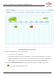
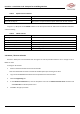
Table 3 Optical Interface Indicators
Optical Indicator Behavior
Description
Turns green and stays lit
Normal
Turns red and stays lit
Optical path is not synchronized or optical module has not been inserted
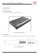
In Figure 3-2, “10” points to the STATUS indicator on the front panel of the AU. Table 4 lists the indicator’s behaviors
and their meaning.
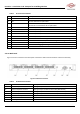
Table 4 STATUS Indicator
STATUS
Description
Flashes green
Device runs Normally
Turns green and stays lit
Software has crashed, but it can reboot automatically in 3mins
Flashes red
Device alarms, need check
Turns red and stays lit
Software has crashed, but it can reboot automatically in 3mins
Flashes yellow
Program is upgrading
Turns yellow and stays lit
Device is starting
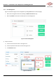
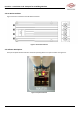
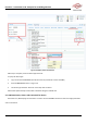
3.6. Master / Slave AU Selection
Each AU is factory-set to be the Master AU. See Figure 3-6 and the procedure below to set or change an AU to
Master or Slave.
To change an AU to Slave:
1. Power on the AU which will be set to be the Slave AU.
Note: The selected AU cannot be connected to the IDAS system prior to being set to Slave.
2. Log in to the AU WebOMT. See Section 0 for the procedures to access the OMT.
3. Select the Engineering tab.
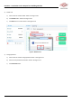
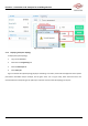
4. In the Advanced Command area, click the drop-down menu for the Master-slave AU select command and
select Slave AU from the drop-down menu.
5. Click Set in the pop-up window.