
User's Manual

CrossFire – A revolution in RF Transport for In Building Wireless
User Manual
73 Revision 1.0.1
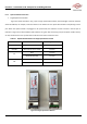
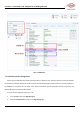
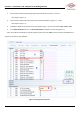
Figure 6-15 Optical SYNC Status
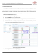
6.4.2. AU connections
Prior to attempting the AU connections, read Section 3 thoroughly.
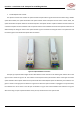
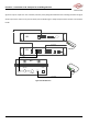
The AU has eight optical ports, designated by eight silk-screened images: “AU1”, “AU2”, “OP1/AU”, “OP2”, “OP3”,
“OP4”, “OP5”, “OP6”. The ports “OP1~OP6” all have the same functionality, providing connections to lower level EUs or
RUs. Insert the optical module into any one of the OP1~OP6 ports, then insert the tail of the optical fibre into the
optical module and connect the other end to the lower EU or RU. After the AU and EU/RU are connected and powered
on, the optical interface indicator LED will turn green, which indicates that the devices are synchronized. If the optical
indicator LED does not turn green, check whether the connection direction of the optical fibre is correct and whether the
optical module is inserted tightly.
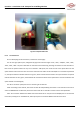
The “AU1” and “AU2” optical ports are for connecting to the slave AU.
When connecting to the slave AU, first access the slave AU independently (see Section 2.2 for instructions on how to
access the WebOMT for the Slave AU). Ensure the status of the AU is “Slave AU” and then connect the optical fibre.
Note: The connection between the Master AU and the Slave AU can only be from the OP1/AU port on the Slave AU
to the AU1 (or AU2) port on the Master AU; other optical ports are invalid for Master-Slave AU connections.