
User's Manual

CrossFire – A revolution in RF Transport for In Building Wireless
User Manual
48 Revision 1.0.1
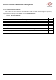
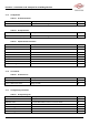
SN
Interface Name
Description
3
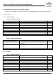
OP1
Connects RU via optical fiber
4
OP2
Connects RU via optical fiber
5
OP3
Connects RU via optical fiber
6
OP4
Connects RU via optical fiber
7
OP5
Connects RU via optical fiber
8
OP6
Connects RU via optical fiber
9
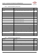
GE1
LAN signals or S1 signals input via CAT-5(STP)
10
GE2
LAN signals or S1 signals input via CAT-5(STP)
11
GE3
LAN signals or S1 signals input via CAT-5(STP)
12
GE4
LAN signals or S1 signals input via CAT-5(STP)
13
GE5
LAN signals or S1 signals input via CAT-5(STP)
14
GE6
LAN signals or S1 signals input via CAT-5(STP)
15
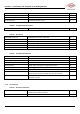
CONSOLE
Connection for local PC through CAT-5 for local monitoring
16
AP
Connection for WLAN Network adapters for monitoring device through Wi-Fi
17
DEBUG
Connection for local debugging PC through USB wire
18
STATUS
Indicates device operating status
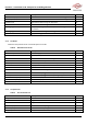
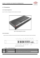
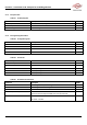
4.3. EU Back Panel
Figure 4-3 shows a schematic of the back panel of the EU and Table 23 lists the interfaces and their functionality.
Figure 4-3 Back Panel of the EU
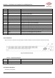
Table 23 EU Back Panel Interfaces
SN
Interface Name
Description
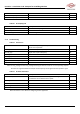
19
Electrical Power Line Interface
/
20
Grounding
/
4.4. Indicator Description
See Section 3.5 for details.