
SlabHeat Installation Manual


16
Ground
Black
Black
White
White
White
White
Line 1
Load 1
Load 2
Line 2
120 VAC or 240 VAC
Sensor Wire
(no polarity)
120 VAC or 240 VAC Heating Cable
(maximum 15 amps)
Two or more120 VAC or
240 VAC Heating Cables
(maximum 15 amps)
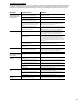
CAUTION: Make sure 120 VAC
is supplied to 120VAC cables and
240VAC is supplied to 240VAC
cables. Otherwise, dangerous
overheating and possible fire
hazard can result.
120/240 VAC
SunStat Control
Ground
Black
Black
White
White
White
White
Line 1
Load 1
Load 2
Line 2
120 VAC or 240 VAC
Sensor Wire
(no polarity)
120/240 VAC
SunStat Control
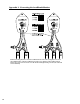
Typical Electrical Wiring Diagram with SunStat Control (120/240VAC)
Dedicated 120 or 240VAC, 20-amp (maximum) circuit.
Typical Electrical Wiring Diagram with SunStat Control (120/240VAC)
Dedicated 120 or 240VAC, 20-amp (maximum) circuit.
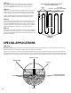
Appendix 1: Typical Electrical Wiring Diagrams (120 and 240 VAC)
All electrical work must be done by a qualified licensed electrician in accordance with local building and electrical codes, and the
National Electrical Code (NEC), especially Article 424, Part IX of the NEC, ANSI/NFPA70 and Section 62 of CEC Part 1.
Ground
Black
Black
White
White
White
White
Line 1
Load 1
Load 2
Line 2
120 VAC or 240 VAC
Sensor Wire
(no polarity)
120 VAC or 240 VAC Heating Cable
(maximum 15 amps)
Two or more120 VAC or
240 VAC Heating Cables
(maximum 15 amps)
CAUTION: Make sure 120 VAC
is supplied to 120VAC cables and
240VAC is supplied to 240VAC
cables. Otherwise, dangerous
overheating and possible fire
hazard can result.
120/240 VAC
SunStat Control
Ground
Black
Black
White
White
White
White
Line 1
Load 1
Load 2
Line 2
120 VAC or 240 VAC
Sensor Wire
(no polarity)
120/240 VAC
SunStat Control
Ground
Black
Black
Black
White
White
White
Line 1
Load 1
Load 2
Line 2
120 VAC or 240 VAC
Sensor Wire
(no polarity)
120 VAC or 240 VAC Heating Cable
(maximum 15 amps)
Two or more120 VAC or
240 VAC Heating Cables
(maximum 15 amps)
CAUTION: Make sure 120 VAC
is supplied to 120VAC cables and
240VAC is supplied to 240VAC
cables. Otherwise, dangerous
overheating and possible fire
hazard can result.
120/240 VAC
SunStat Control
Ground
Black
Black
Black
White
White
White
Line 1
Load 1
Load 2
Line 2
120 VAC or 240 VAC
Sensor Wire
(no polarity)
120/240 VAC
SunStat Control
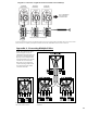
Typical Electrical Wiring Diagram with SunStat Control and Relay(s)
Dedicated 120VAC or 240-VAC, 20-amp (maximum) circuit.
Two or more120 VAC or
240 VAC Heating Cables
(maximum 15 amps)
2-Conductor
18 to 24 AWG
Signal Wire
Ground
Black
Black
Black
White
White
White
Line 1
Load 1
Load 2
Line 2
120 VAC or 240 VAC
Sensor Wire
(no polarity)
120/240 VAC
SunStat Control
Two or more120 VAC or
240 VAC Heating Cables
(maximum 15 amps)
Ground
Black
Black
Black
White
White
White
Line 1
Load 1
Load 2
Line 2
120 VAC or 240 VAC
120/240 VAC
SunStat Relay
Relout
2
3
4
5
RelinRelin
Relout
2
3
4
5
RelinRelin
Relout
Setback
Sensor
2
3
4
5
Relout
Relin
Relin
Relout
RelinRelin
Relout
120/240 VAC
SunStat Relay
120/240 VAC
SunStat Relay
Up to 10 SunStat Relays
can be connected to
one SunStat Control
120/240 VAC
SunStat Control
Observe polarity when connecting relays