
SlabHeat Installation Manual


10
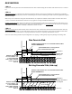
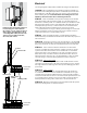
Splice, not in
conduit
Power Lead
Heating Cable
Install an extra-deep single-gang box
if connecting one or two cables to
the control. Use a 4"-square deep box
with a single-gang mud ring cover if
connecting three cables, because the
extra room is needed for the wire,
wire nuts, and control.
Electrical
See wiring diagrams in Appendix 1 for different voltages and applications.
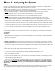
OVERVIEW We recommend the floor-warming system be installed on a
dedicated circuit coming directly from the circuit breaker panel. Follow all
National Electric Code (NEC) and other local electrical code requirements
when installing this system. Work should be done with great care and
with the power turned off to the circuit being worked on.
STEP 2.8 Install a maximum 20-amp circuit breaker(s) into the breaker
panel, depending on the load of the system. Use a 120-VAC single-pole
breaker for a 120-VAC system. Use a 240-VAC double-pole breaker for a 240-
VAC system. The SunStat control comes with built-in Ground Fault Circuit
Interrupter (GFCI) protection, so a GFCI breaker is not needed. However,
install a GFCI type breaker if another type of control is to be used.
For systems that are too large to directly power through one control but
must be operated by one floor-sensing control, use a SunStat control in
combination with up to 10 SunStat Relay controls.
STEP 2.9 Install a Listed Electrical Box. Consult with the installation
manual that was provided with the thermostat to determine the proper box
size and location.
STEP 2.10 Following local electric code, feed 14-gauge or 12-gauge NM
type electrical wiring from the circuit breaker panel to the control electrical
box. Leave about 6"–8" of extra wire extended from the box to work with.
STEP 2.11 If the control box must be mounted in a location that is
too far to reach with the power lead wires, it will be necessary to mount
a junction box where the lead wires can be terminated. Use a standard
junction box with a cover, mounting it in an easily accessible location. It
must remain easily accessible and not located behind a wall, cabinet, or
similar obstruction. Then use 14- or 12-gauge NM type or other accepted
electrical wiring to connect from the junction box to the control box.
STEP 2.12 Power Lead Conduit
Install a minimum of 3/4" rigid or flexible Listed conduit from the control
electrical box or junction box to the slab location. Extend it 2" to 6" into the
slab edge and attach a bushing to the end to prevent damaging the cable
power leads.
STEP 2.13 Sensor Conduit
The SunStat sensor is designed to be embedded in the slab. However, it
is recommended that the sensor be installed in a minimum of 1/2" rigid
or flexible Listed conduit for added protection. If the end of the conduit is
sealed, this would allow the sensor to be removed and replaced if there ever
is a problem. Install so that the sensor tip is located 1" below the surface,
half-way between heating cables, and at least 1' into the heated area.
STEP 2.14 Mark the circuit breaker in the panel which feeds the system
with “Floor warming/bath" or similar description.
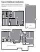
Concrete slab
Insulation
Concrete slab
Gravel base
Foundation Wall
Gravel base