Series SH Installation Manual Please note that local codes may require this product and/or the control to be installed or connected by an electrician.
Welcome to SlabHeat Cable SlabHeat products are a simple way to heat a given space. This instruction manual is provided as a guide to installing SlabHeat Cable, including design considerations, cable installation, control installation, precautions, and floor covering guidelines. Specifications for SlabHeat Cable: SlabHeat Cable is a complete heating cable consisting of a series resistance heating cable and a single power lead for easy singlepoint connection. The heating cable length cannot be cut to fit.
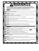
WARNINGS Installation must be performed by qualified personnel, in accordance with local codes and standards. A licensed electrician is recommended. Read these important warnings and all installation instructions prior to installation. Failure to so do can result in fire, shock, property damage, personal injury and/or death. NEVER NEVER cut or modify the heating cable. The power lead may be cut shorter if necessary, but never removed from the heating cable. NEVER bang a trowel or other tool on the cable.
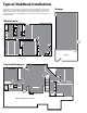
Typical SlabHeat Installations The illustrations on this page show some of the typical installation locations of SlabHeat. In addition to these, SlabHeat is also well suited for any kind of home addition with concrete slab. It's perfect for a bedroom addition, a sun room, a detached garage, or an extended living area. SlabHeat also works well for use in commercial areas.
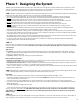
Phase 1: Designing the System SlabHeat cable should be installed in all interior floor areas that are to be warmed. It cannot be used for exterior applications, snow melting, or in ceilings. In many applications, it can be used to heat the room as well, but an accurate heat-loss calculation must be made to determine if enough heat will be provided to match the heat loss of the room. STEP 1.1 Make a sketch of the room.
STEP 1.5 Select the cables you need. WATTAGE: Decide what heat output is required. Your design must consider the size of the space being heated as well as the heat loss for the space. 15 watts per square foot: sufficient for sun room floors, basements, bathrooms, and kitchens 10 watts per square foot: sufficient for hallways, entry ways, and large areas with low heat loss SIZE: Select a cable in Table 2 to fit the heated area measured in Step 1.3.
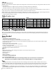
INSPECT CABLE, CONTROL, and SENSOR CAUTION: Make sure power is not applied to the product until it is fully installed and ready for final testing. All work must be done with power turned off to the circuit being worked on. STEP 2.1 Remove the SlabHeat Cable, control, and sensor from their packages. Inspect them for any visible damage and verify everything is the correct size and type according to your plan and order. Do not attempt to install a damaged product. STEP 2.
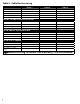
Table 4 - Cable Resistance Log Cable 1 Cable 2 Cable 3 Cable serial number Cable model number Cable voltage Cable resistance range Sensor OUT OF THE BOX BEFORE INSTALLATION Cable white to white Cable white to ground Cable white to ground Sensor AFTER CABLE IS SECURED IN PLACE Cable white to white Cable white to ground Cable white to ground Sensor AFTER SLAB IS POURED Cable white to white Cable white to ground Cable white to ground Sensor Retain this log to retain the warranty! Do not discard! 8
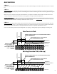
BASE MATERIAL STEP 2.5 Prepare the site that you want to heat with SlabHeat Cable. This includes making sure all utilities and obstructions are accounted for. STEP 2.6 New concrete slab: Lay a smooth, well-compacted gravel base. Ensure proper slope and drainage as required by local building codes to avoid water buildup in any heated or surrounding areas. Follow local building code and construction guidelines for grade thickness and type.
Electrical See wiring diagrams in Appendix 1 for different voltages and applications. OVERVIEW We recommend the floor-warming system be installed on a dedicated circuit coming directly from the circuit breaker panel. Follow all National Electric Code (NEC) and other local electrical code requirements when installing this system. Work should be done with great care and with the power turned off to the circuit being worked on. STEP 2.
Phase 3: Installation of Cable The following Steps 3.1 through 3.9 cover installation basics. Step 3.10 covers some specific applications and their special requirements. BASIC INSTALLATION STEP 3.1 Determine a time to install the cable when equipment, heavy tools, and site traffic will be minimal to keep from possibly damaging the product. Be prepared to apply the surfacing courses over the cable the same day so it will be protected from damage.
STEP 3.6 Use a digital multi-meter to measure the resistance between the conductors of the cable power leads again. Record these resistances in Table 4 under “After cable is secured in place". STEP 3.7 Top-Down view of SlabHeat cable and the slab sensor entering slab. Conduit Factory Splice (in concrete, not in conduit) Power Lead Feed the power leads through the conduit into the junction box, leaving at least 6 inches of free lead length.
Phase 4: Finish Coverings STEP 4.1 Before beginning work, inspect the cable for damage and secure any cable that may have come loose. To avoid burying any possible damage that may have occurred since the cable was laid, the following tests should be performed: Use a digital multi-meter to measure the resistance between the conductors of the cable power leads again (see Step 2.3). Your electrician should perform an insulation resistance test on the cable. A megohmeter (e.g.
Phase 5: Controls and Sensors Refer to Typical Wiring Diagrams on pages 16 and 17. STEP 5.1 De-energize all circuits feeding this system before doing any electrical work. STEP 5.2 If necessary, make wire connections at junction boxes for the SlabHeat Cable power leads to the power wiring from the control. STEP 5.3 Install the control at its location according to the instructions provided with the control. Make wiring connections to the power source and to the sensor wires and cable lead wires.
Troubleshooting Guide If problems with the system arise, please consult the troubleshooting guide below. Any troubleshooting work should be done with the power removed from the circuit, unless otherwise indicated. An electrician should perform any troubleshooting involving wiring, connections, and testing that requires power to be applied. Problem Possible Cause Solution Cable resistance measurement is outside the range printed on the nameplate label.
Black Black Line 1 Black Black 120 VAC or 240 VAC 120 VAC or 240 VAC Heating Cable Sensor Wire (maximum 15 amps) (no polarity) Sensor Wire (no polarity) 120 VAC or 240 VAC (maximum 15 amps) AppendixWhite1: Typical Electrical Wiring Diagrams Load 2 (120 and 240 VAC) Line 2 Load 2 LineWhite 2 White White White White Typical Electrical Wiring Diagram with SunStat Control (120/240VAC) Dedicated 120 or 240VAC, 20-amp (maximum) circuit.
Diagram for connection of signal wire between SunStat Control and Relays 120/240 VAC SunStat Relay Relin 120/240 VAC SunStat Relay Relout Up to 10 SunStat Relays can be connected to one SunStat Control Relin Relin Relout Relout Relin 120/240 VAC SunStat Control Relin Relout 2 3 4 5 Setback 2 3 4 5 Relin Relin Relout 2 3 4 5 Relin Relout Sensor Observe polarity when connecting relays All electrical work must be done by a qualified licensed electrician in accordance with local building a
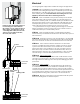
Appendix 3: Connecting the LoudMouth Monitor Illustrations showing (left) how to connect the LoudMouth monitor to two cables, and (right) how to connect the LoudMouth to three cables. The LoudMouth can monitor no more than three cables simultaneously. Do NOT leave the power leads connected in “series” like this when making final wiring connections; the cables will not heat sufficiently.
Electric Indoor Slab Heating Products 10-year Limited Warranty Watts Regulator Co. d/b/a Watts Radiant (Watts Radiant) warrants its electric slab heating cable (the Product) to be free from defects in materials and workmanship under normal usage for ten (10) years from the date of manufacture. Thermostats and controls sold by Watts Radiant are warranted, parts and materials, to be free from defects in material and workmanship for two (2) years from the date of purchase.
4500 E. Progress Place Springfield, MO 65803 Phone: (417) 522-6128 Fax: (417) 831-4067 Toll Free USA, Canada: (888) 432-8932 On the Web: www.suntouch.