
Install Instructions

Installation
The PM-5 must be installed in a location that exposes the moisture grid
to a clear view of the sky and any precipitation. The unit should not be
mounted directly under eaves, overhangs, or other obstructions that can
block precipitation from reaching the moisture grid.
Do not install the sensor close to the ground, or any other location, that can
cause the sensor to be buried in snow.
Mount the PM-5 outdoors, away from furnace vents, dryer vents, and other
sources of heat. The PM-5 can be mounted to a free-standing conduit or
by using the mounting holes in each corner of the enclosure.
Do not drill holes in the enclosure.
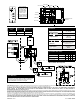
Wire the controller in accordance to the provided schematics.
Operation
Before installing and wiring the
PM-5 sensor, it is important to
set all power and control settings
prior to wiring or mounting.
1. Set the voltage jumpers to
correspond with the supplied
power. Place jumpers on the
outside two posts for 120 VAC
and a single jumper on the
inside two posts for 208 or
240 VAC.
2. Set the Temp Adjust control for desired melting
conditions. Precipitation below this temperature is
assumed to be snow, above rain. Control comes with
the Temp Adjust dial set to 39°F (4°C).
3. Set the Delay (DEL) time for 30, 45, 60, 75, or 90
minutes. The Delay function will allow the snow melt
system to run for the set time frame after moisture is
no longer detected (once snowfall has stopped). This
is to help prevent "black ice" from forming.
IS-WR-PM5
Instructions for Installing PM-5
Remote snow/ice sensor
The PM-5 is a multi-voltage, self contained temperature, snow and
ice sensor control. Each PM-5 can be set to operate with either 120,
208, or 240 VAC and can provide up to 60 amps of service to the load
(2 circuits 30 amps each). The integrated snow sensor is heated to allow
for snow, ice, or freezing rain to melt, allowing proper detection of
environmental conditions.
4. Determine how the sensor operates by setting the toggles located at
S1.
Snow: The control will operate when precipitation is
detected below the Temp Adjust setting.
Recommended ON.
Rain: The control will operate when precipitation is detected above the
Temp Adjust setting. Required OFF.
DEL: The control will operate with a Delay Off time. If this function is
set to Off, the control will operate with a 2 minute delay to prevent
short-cycling of external components.
Recommended ON.
LTC: The control will operate in Low Temperature Cutoff mode,
preventing operation when Ambient Temperatures (AT) fall
below 15°F (9.5°C).
Recommended: ON (for systems with limited heat output).
Power must be cycled for switch changes to take effect.
Manual Override Switch
An override switch is mounted on the side for testing and special
operational requirements. Placing the switch in the "Automatic" position
will allow the sensor to operate normally. "Manual On" will activate the
control and will stay activated for a maximum of 40 hours before returning
to "Automatic" mode. The "Stand-by/Reset" position will clear any current
snow melt call or delay activity.
If the Manual Override Switch is moved to Manual On for less than 2
seconds and then back to Automatic the sensor will execute one delay
off cycle. This can be used to clear frost, hail, drifting snow, or other
conditions. Stand-by/Reset will clear this setting.
IND. CONT. EQ.
LISTED
11TN
USC
R
ENCLOSURE TYPE 3R
�
�
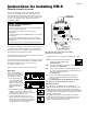
PM-5 provides integrated air and moisture detection within a
rainproof and ice-resistant enclosure.
Air Temperature Sensor
Wiring Access
Control Switch
Moisture Grid
SNOW
RAIN
DEL
LTC
120 240 120
R2B R1B
R1A
R2A
Z2
Z1
SNOW
RAIN
DEL
LTC
120 240 120
R2B R1B
R1A
R2A
Z2
Z1
SNOW
RAIN
DEL
LTC
120 240 120
R2B R1B
R1A
R2A
Z2
Z1
SNOW
RAIN
DEL
LT C
120 240 120
R2B R1B
R1A
R2A
Z2
Z1
!
WARNING: General Safety Instructions
1. THIS UNIT SHOULD BE INSTALLED ONLY BY
QUALIFIED PERSONNEL!
2. Disconnect all power from the control, or any associated equipment,
before opening the front cover plate.
3. Confirm power selection jumpers are properly set prior to
applying power.
4. To avoid fire hazard, replace fuse only with 2 Amp 32 V or 250 V 3AG
fast acting fuse.
5. Do not drill holes through the electrical enclosure for mounting.
Mount the control to a free-standing conduit or via the pre-determined
mounting holes.
6. Ensure front cover gasket is properly installed when replacing cover.
SNOW
RAIN
DEL
LTC
120 240 120
R2B R1B
R1A
R2A
Z2
Z1