
Install Instructions
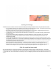
Table Of Contents
- Repair-SunTouch-Heating-Wire-Instructions-Manual-Current-WYF
- wr_electricfloorwarming_instructions_repairtips-en
- ADDITIONAL TIPS
- V.1 5/24/05
- Disclaimer: The following are tips and techniques provided by Watts Radiant, Inc. to assist in discovering and uncovering damage made on-site to an electric radiant heating system product made by this company. Watts Radiant does not, in any way, guaran
- Finding damage within floor warming systems
- Spotting the damage

Step 3.13. Pull the heating wires
together to overlap the heating ele-
ments of both leads. Lightly twist the
elements together to better join them.
Slide the solder tube over the twisted
elements, centering the elements
between the gray adhesive bands. If
this is not done correctly, the elements
may pull out and cause the splice to fail.
Step 3.14. Use the heat gun (set to HI
temperature, about 1000°F) to carefully
heat the solder tube. First, heat directly
under the solder ring in the middle
of the tube. IMPORTANT! When the
solder completely melts and flows into
the wires, continue heating for another
3 seconds. If the heat is removed too
soon, an incomplete solder connection
will result, causing connection failure
later. When the solder is completely
melted, begin moving the heat gun
back and forth under the rest of the
solder tube to shrink the tube and cause
the adhesive bands at the ends to melt
and flow onto the wire insulation. After
the tube is completely shrunk and the
adhesive bands are fully melted, stop
heating the tube. Additional heating
will not help and may cause either
scorching of the tube or splice failure.
Allow the solder tube to cool for about
1 minute.
Step 3.15. Repeat Steps 3.12 through
3.14 for the other heating wire splice.
Make sure to avoid reheating or
scorching the first splice while working
on the second. It may require a heat
shield like a wet cotton rag or a piece
of tin to protect the first splice and the
insulation of the heating wires.
Step 3.16. Slide a ground solder tube
over a ground braid lead. Overlap the
braid ends and twist them to help hold
them together. Slide the ground solder
tube over the twisted braid ends, cen-
tering them under the ring of solder.
Step 3.17. Be sure to avoid reheat-
ing or scorching the heating wires or
splices, using a heat shield again if
needed. Heat the tube to shrink it com-
pletely and cause the solder to flow into
the twisted ground wires completely.
When it cools, the connection should
be secure.
Step 3.18. The connection should now
be complete and ready to test. Go to
Step 5.1 under “Testing the Repair.”
Step 4.1. Cut out a 2”- to 3”-long sec-
tion of the heating cable around the
damaged area, creating two ends or
leads.
If the cable is not a jacketed heating
cable, SKIP to Step 4.6.
Some of our products have an “XLPE”
jacket that is a somewhat hard mate-
rial that can be lightly “scored” with a
scoring tool or sharp blade. Use the
scoring tool to carefully score the jacket
about 2.5” from the end of each lead.
Do this by placing the cable lead into
the V-notch of the tool and rotating the
tool only one or two revolutions around
the cable. Do not place any additional
pressure on the tool head to cut deeper.
Let the tool apply its own spring-loaded
pressure.
Step 4.2. For a heating cable with an
outer jacket: Strip off approximately
2.5 inches of the outer jacket. DO NOT
USE standard wire strippers! The out
of round character of the cable makes
it very difficult to strip with a common
wire stripper tool, using one could dam-
age the cable. There are two types of
jacket compounds, “XLPE” and “TPU”
(TPU see Step 4.3.b).
Part 4. Installing a
Jumper Splice
Step 4.3. Gently bend the cable at the
score to break through the jacket all
the way around the cable, then pull off
the slug.
Step 4.3.b. If the jacket is the softer
“TPU” material, you’ll find it is easier to
use thermal wire strippers or the tip of
a soldering pencil to melt a narrow ring
around the outer jacket of the cable,
then pull the slug off. The TPU jacket
has a lower melt point than the insula-
tion on the heating elements, but you
must still be very careful to avoid over-
heating the insulation on the elements
during this step.
Step 4.4. With either type of jacket, if
the jacket slug doesn’t easily pull off you
may need to use your heat gun to gen-
tly warm the slug, which should soften
and loosen it for you. Use the heat gun
(set to about 500°F) and move the gun
back and forth under the jacket slug for
about 3 or 4 seconds, or until it can be
easily removed.
Step 4.5. Use a glove or other protec-
tive cloth to pull off the loosened jacket
slug. Do not touch the hot jacket slug
with bare fingers. The slug will be very
hot and will burn!
Step 4.6. Loosen the braid by pushing
back on the braid about 1/2”, causing the
ends of the heating wires to be exposed.
Step 4.7. Bend the cable back onto
itself.
Step 4.8. Use the small screwdriver,
paper clip, fingernail, or similar instru-
ment to pry between the braid and
make an opening through which to
pull the heating wires. Pull each wire
through the braid.
Heating Cable Repair Kit Guidelines 3