
Product Overview

n
o
s
r
n
p
p
q
TECHNICAL DATA
General
Mounting Flange mounting
Connection threads
Inlet and return 1/4 NPTF
Nozzle outlet 1/8 NPTF(model A2VA3006)
3/8x45° flare tube fitting (model A2VA3106)
(refer to "Pipe Dimensions" drawings)
Pressure gauge port 1/8 NPTF
Bleeder valve port 1/8 NPTF
Valve function Pressure regulation and cut-off (cut-off
function only assured for specified pressure
range)
Cut-off Diaphragm and solenoid
Strainer 3 GPH
Shaft 5/16 in
By-pass plug Not inserted in return port, for one pipe system.
To be inserted in return port with a 5/32 Allen
key for two-pipe system.
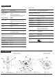
PUMP DIMENSIONS
We reserve the right to change specifications without prior notice.
Hydraulic data
Nozzle pressure range 100 - 150 psi (#2 and lighter fuel)
150 - 200 psi (#2 fuel only)
Delivery pressure setting 100 psi
Rated nozzle flow 4 GPH @100 psi, 3450 rpm
3 GPH @150 psi, 3450 rpm
Oil temperature 50 - 115 F
Inlet pressure 10 psi max.
Return pressure 10 psi max.
NFPA limits pressures to 3 PSI max.
Suction height Single pipe : 6" Hg max. vacuum,
two-pipe : 12" Hg max. vacuum,
to prevent air separation from oil
Power consumption 70 W @100 psi
90 W @150 psi
Rated speed 3450 rpm max.
Recommended motor 60 Hz
frequency
Certified
A-3000 - US - Ed. 2 - Dec. 2014
Solenoid valve characteristics
Solenoid valve voltage 110-120 V ; 50/60 Hz
Consumption 9 W
Ambient temperature 50 - 115 F
Maximum pressure 200 psi
Inlet
n
Nozzle outlet
p
Pressure adjustment
q
Bleeder valve
r
Cone valve
s
Return and
internal by-pass plug
o
Model A2 VA 3106
special nozzle outlet
Model A2 VA 3006
standard nozzle outlet