SUNSTONE® POWER CIRQUE™ Read all instructions before you operate your grill. Save these instructions! Conforms to ANSI STD Z21.58-2018 Certified to CSA STD 1.6-2018 Outdoor Cooking Gas Appliances 3174816 To installer or person assembling grill: Leave this manual with grill for future reference. To consumer: Keep this manual for future reference. www.sunstonemetalproducts.
Welcome & Congratulations Congratulations on your purchase of a new Sunstone grill! We are very proud of our product and we are completely committed to providing you with the best service possible. Your satisfaction is our #1 priority. Please read this manual carefully to understand all the instructions about how to install, operate and maintain for optimum performance and longevity. We know you’ll enjoy your new grill and thank you for choosing our product. We hope you consider us for future purchases.
INDEX DIRECTORY BURNER PARTS LIST SUN24PCB ----------------------- 1-2 HAZARDS & WARNING SIGNS BURNER INSTALLATION Product Detail --------------------Cut-Out Detail ----------------------GFCI Transformer----------------- 3 4 ---------Install & Placement--------------Open Area-------------------------Recessed Position----------------- 6 7 8 5 ISLAND LOCATION Overhead Structure------------- 9 Enclosed Install------------------- 10-11 GAS SETUP Installation Overview -------------------------Large C
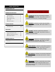
START-UP CHECKLIST ATTENTION: Never operate the grill unattended. EXPLOSION: When Igniting the Grill – Always keep the Hood Open. “FIRST TIME STARTUP CHECKLIST” Transformer Electrical Plug is properly installed. Installation of the proper gas type and regulator settings. The proper Regulator & Gas Connection is complete. Minimum 24” Inch to Combustible Clearances are maintained. All packaging has been removed from Interior of Grill All parts and components are properly installed.
BURNER PARTS LIST – PARTS DIAGRAM PAGE 1 MATERIAL SPECIFICATIONS 18 Gauge 304 Stainless steel for 19" Burner. 16 Gauge 304 Stainless steel for Griddle. 20 Gauge 304 Stainless steel for Hood 18 Gauge 304 Stainless steel body and control panel, 20 gauge 304 for drip tray. 201 Stainless steel for manifold.
BURNER PARTS LIST – PARTS DIAGRAM PAGE 2
BURNER INSTALLATION – PRODUCT DETAIL PAGE 3 Product Details The Power Cirque Burner consists of multiple insert options, each with its own unique purpose and functionality. The Large cover, 20” Dia. Three-in-one Cooking Grid, and 15” Dia. Pizza Stone are all included with the base model. Only the optional Pot Filler and 19” Dia. Griddle & Oil-Pan are sold separately.
PAGE 4 BURNER INSTALLATION – CUT-OUT DETAIL Cut-Out Details It is always best to first have the Burner On-Site, if you cannot make sure to follow all Cut-Out instructions exactly as shown. The Burner is SELF-RIMMING, meaning the lip of grill rests on top of the counter edge around the cut-out with the front of grill which is Free Hanging from countertop. Because of this, there is No Need for any Trim-Kit like with many other grills in the market.
BURNER INSTALLATION – GFCI TRANSFORMER PAGE 5 LIVE CIRCUIT: Use only with a Ground-Fault Circuit Interrupter - GFCI protected Outlet with this Power Burner. VOLTAGE: Use only extension cords approved for outdoor use marked with W-A and rated for the power of this appliance. 1. Locate the transformer Remove the transformer from the plastic bag located in the interior of burner.
BURNER INSTALLATION – INSTALL & PLACEMENT PAGE 6 Install & Placement Your grill is SELF-RIMMING, meaning the lip of grill rests on top of the counter edge around the cut-out with the front of grill which is Free Hanging from countertop. Because of this, there is No Need for any Trim-Kit like with many other grills in the market.
PAGE 7 BURNER INSTALLATION – OPEN AREA Open Area Counter-Top Install 1. For breezy days, be careful not to leave the cover on for more than 15 minutes, when the burners are on HIGH Heat. (Never leave grill unattended when in operation) 2. If you suspect the grill is overheating, using an oven mitt, remove the hood. Then turn the burner control knob to off position. 3.
PAGE 8 BURNER INSTALLATION – RECESSED POSITION Recessed Position Install When installed as Recessed Position, this is most often used for Large Crock Pot Cooking, by lowering the height of the cooktop this makes it easier to maneuver heavy pots on and off. We recommend elevating the counter 8” to 12” lower and leave a minimum of 2” clearance on either side so that you have 1” clearance beyond the edge of burner.
ISLAND LOCATION – OVERHEAD STRUCTURE PAGE 9 Overhead Structure Definition: Structure built above Appliance that is sometimes attached to the home’s exterior outside wall or roof and there is a Minimum of “Two” adjacent sides which are open with outside exposure. Minimum Distances to Combustible Materials or other Appliance ONLY, Non-Combustible materials do not apply! (A) From Floor to Overhead Combustible Structure 8’ Min. Clearance (B) From Counter to Overhead Combustible Structure 5’ Min.
ISLAND LOCATION – ENCLOSED INSTALL Enclosed Installation Definition: PAGE 10 Structure built above Appliance that is attached to the home’s exterior outside wall, roof or is inside a separate structure like outdoor room and there is a Minimum of “One” Side open with outside exposure.
ISLAND LOCATION – ENCLOSED INSTALL PAGE 11 The Table below is referencing Enclosed Install Illustration on page 10 Minimum Distances to Combustible Materials or other Appliance ONLY, Non-Combustible materials do not apply! (A) From Appliance to Vent Hood Width 4” Min. Clearance (B) From Counter to Outdoor Vent Hood 36" Min. Clearance (C) From Floor to Overhead Structure 8’ Min. Clearance (D) From Counter to Overhead Structure 4” Min. Clearance (E) From Appliance to Combustible Material 24" Min.
GAS SETUP – INSTALLATION OVERVIEW PAGE 12 CAUTION: Gas conversion kits are available from Customer care by dialing 888-934-9449. When ordering gas conversion kits, have the model number, and the type of gas (natural or LP). Use only the gas pressure regulator supplied with this appliance. This regulator is set for an outlet pressure of 11 inches water column. An installer-supplied gas shut-off valve must be installed in an easily accessible location.
GAS SETUP – LARGE CAPACITY LP TANKS PAGE 13 ATTENTION: If you have a Side Yard Propane Tank, you MUST have additional Medium Pressure Regulator located at the Grill. If you do not serious bodily harm may result or damage to the grill and island structure from HIGH Heat extremes. Large Capacity LP Tanks Propane is delivered to your home as a very cold liquid and is pumped into a specially designed storage tank which is either Above or Below Ground. The liquid changes to gas before leaving the tank.
GAS SETUP – MEDIUM CAPACITY LP TANKS PAGE 14 Medium Capacity LP Tank The Type 1 connection system has the following features: The system will not allow gas to flow until a positive connection has been made. NOTE: The cylinder control valve must be turned off before any connection is made or removed. The system has a thermal element that will shut off the flow of gas in the event of a fire. The system has a flow limiting device which, when activated, will limit the flow of gas to 10 cubic feet per hour.
GAS SETUP – NATURAL GAS INSTALL PAGE 15 NG Gas Hook-up Natural Gas grills is designed to operate on Natural Gas ONLY, at a pressure regulated at 7” water column (W.C.) when equipped with the correct natural gas orifices on the valves and a NG regulator on the supply line regulated at the residential meter. Follow Instructions: 1. The tank valve & all Knobs should be in the “OFF” position. If not, turn the knob clockwise until it stops. 2.
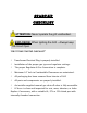
BURNER START-UP – LIGHTING THE POWER BURNER PAGE 16 ATTENTION: Always take a leak test before lighting the grill to prevent a possible fire or explosion. DO NOT smoke while leak testing. Extinguish all open flames. Never leak test with an open flame or risk of serious harm to self or others. WARNING: Never stand with your head directly over the Grill when lighting the Burner, to prevent possible injury. EXPLOSION: Never Operate the Burner Unattended. When Igniting the Grill – Always keep the Hood Open. 1.
SUNSTONE POWER CIRQUE BURNER WARRANTY PAGE 17 ATTENTION: The Power Burner must be installed according to the product manual. If your burner installation does not meet the Basic Setup Instructions ALL WARRANTIES MAY BE VOID. WARRANTY COVERS ORIGINAL PURCHASER ONLY, MUST HAVE COPY OF ORIGINAL INVOICE TO RECEIVE ALL WARRANTIES.