
Operation Manual


15VR2 Contoller Rev.A
ENGLISH
9006377
A
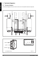
9.2 Technical diagram battery charger
The controller’s standard conguration includes a ‘3-pin connection’. Ensure that the battery charger
is properly connected so that the ‘negative pole’ and the ‘inhibit’ are connected, enabling the system to
prevent the wheelchair from moving when the battery is being charged.
Figure 9
Figure 10
Battery charger
Battery +
Battery -
Inhibit
VR-2 90A Powermodule
VR-2 90A Powermodule twin actuators
mounting holes
motor motor
seat RWD
seat FWD
battery