PC-IP SOFTWARE For the CM100 IP, CM250 IP, and CM500 IP User Manual
Contents PC-IP Software for the CM100 IP, CM250 IP, CM500 IP User’s Manual Version 1.
ii Install Profiler User’s Manual DISCLAIMER Information in this document is subject to change without notice and does not represent a commitment on the part of Sunrise Telecom Broadband, Inc. The software and/or hardware described in this document are furnished under a license agreement or nondisclosure agreement. The software may be used or copied only in accordance with the terms of the agreement.
Contents Contents Chapter 1 General Information ................................................ 1 Install Profiler Configuration ......................................... 1 Measurement Data Management ................................... 2 PC Requirements ............................................................ 2 USB to Serial Port Adapter ....................................................... 2 Software Compatibility ................................................... 3 Preparation for Use .........
iv Install Profiler User’s Manual To Get All Channel Tables ....................................................... 29 Channel Table Information ...................................................... 29 Editing the Channel Table ....................................................... 32 Save ....................................................................................... 36 Copy Table .............................................................................. 37 Print ............................
Contents Chapter 5 Viewing Files ........................................................ 59 View Signal Level Meter Saved File ....................................... 59 Bar Graphs ............................................................................. 60 Analog Channels .......................................................... 61 Digital Channels ..................................................................... 62 View Scan Saved File ...................................................
vi Install Profiler User’s Manual Logon Accounts File ............................................................... 92 Record Log ............................................................................. 92 Send Logon Message ............................................................. 92 Anonymous FTP Access ......................................................... 93 Setting Access Limits .............................................................. 94 Monitoring user activity ...................
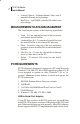
Chapter 1 Software Overview Chapter 1 General Information PC-IP is a licensed software product included with the CM100 IP, CM250 IP, and CM500 IP Install Profiler. The license agreement is similar to most other software license agreements, requiring that it be used for the single installation on one PC and that the only copying rights are for backup purposes.
2 PC-IP Software User’s Manual • • Leakage Option – Leakage channel, limit, unit of measure, distance and tag settings. RealView – realWORX controller IP address and port settings. MEASUREMENT DATA MANAGEMENT The Load feature consists of the following capabilities: • • • • • Load – To view and analyze any of the test results saved in the Install Profiler. Load and Save All – To transfer all saved files from the Install Profiler to the selected PC directory.
Chapter 1 Software Overview For proper operation, the Belkin adapter and software should be installed before your PC-IP software. If necessary, un-install PC-IP and re-install after the USB to Serial port adapter software is installed. SOFTWARE COMPATIBILITY Install Profiler firmware may be updated free of charge at the Sunrise Telecom website using a computer meeting the requirements above along with a modem and appropriate Internet browsing ability.
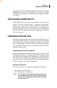
4 PC-IP Software User’s Manual Registration The PC-IP software is a licensed software package intended for installation on one PC and should not be copied, installed on multiple computers, servers or distributed. See the license agreement for detailed information. To register and receive the license key, go to the Sunrise Telecom web page at: www.sunrisetelecom.com/broadband and click on the register software icon. Registering your software helps us notify users of new updates and provide support.
Chapter 1 Software Overview No other warranty is expressed or implied. Sunrise is not liable for consequential damages. From time to time, Sunrise may release updates or improvements to the PC-IP software. While upgrades and options may require an additional charge, updates to the base PC-IP software will be available for download from our web site without charge during the warranty period.
6 PC-IP Software User’s Manual
Chapter 2 Getting Started Chapter 2 Getting Started WHAT YOU WILL NEED To complete the installation and operation of the PC-IP software, you should have the following items at hand when you start. PC-IP software package (CD-ROM) PC-IP User’s Manual Install Profiler Install Profiler Charger Install Profiler User’s Manual Serial straight-through cable (supplied with Install Profiler) PC as outlined in the Compatibility section.
8 PC-IP Software User’s Manual 3. When the window for the CD-ROM files opens, click on the setup program, PC-IP setup.exe, and click Enter. A Welcome screen will be displayed (Figure 2-1). Click on Next to continue. Figure 2-1 4. In the Setup window, read the instructions and License Agreement, then click YES or NO. Click YES if you agree to the License requirements and NO if you do not agree. Clicking NO will abort the installation process.
Chapter 2 Getting Started 5. The initial process is to check the PC for existing copies of PC-IP and to begin extracting files, the screen (Figure 2-3) will be displayed during this process. Figure 2-3 6. When the Customer Information screen is displayed, enter your user name and company.
10 PC-IP Software User’s Manual 7. On the Choose Destination Location screen, accept the proposed file directory or enter a new one and click Next. Figure 2-5 8. Accept the proposed shortcut folder location or select a new one as shown in Figure 2-5 and click Next.
Chapter 2 Getting Started 9. When the Select Components screen is displayed, select Next to continue the installation. All components are required for the PC-IP installation. Figure 2-7 10. As shown in Figure 2-8, the installation program is now ready to copy the program files to your computer and setup the appropriate drivers and icons. Click Next to complete the installation.
12 PC-IP Software User’s Manual 11. Following the file transfer shown, display will provide a Windows message that “Install Shield Wizard Complete”. Click on Finish. Figure 2-9 12. To establish a shortcut for the PC-IP software, click on the Windows™ Start button, select programs, hold down Control and drag the PC-IP icon to the desktop or program launch bar. See the next chapter on operating your new PCIP Software.
Chapter 3 Using PC-IP Software Chapter 3 Using the PC-IP Software Opening the Install Profiler Software Following installation, the PC-IP Software will open, close and operate like any other Windows™ based software on your computer. To open the PC-IP software, click Start on the Windows™ Task Bar, click on Programs and click on PC-IP Software. To un-install the PC-IP software, simply run the install program again. The PC-IP software may be used 10 times before entering the software key.
14 PC-IP Software User’s Manual When the software key is obtained, type or copy it into the box labeled “Software Key” and click on the Key button. Until you obtain the software key, you may bypass the key requirement by clicking on the Bypass button. Each time you use the PC-IP in the Bypass mode, your “Number of Unregistered Runs Remaining” will decrement by one. To close the screen without using one of your “Unregistered Runs”, click on Cancel.
Chapter 3 Using PC-IP Software SOFTWARE OVERVIEW The PC-IP software allows to direct interfacing with the Install Profiler via the RS-232 connection. It provides the ability to download saved data, check the Install Profiler configuration, download, upload and edit channel tables, configure the cable modem, select the automated tests to perform and set the pass/ fail limits and to clone one Install Profiler’s configuration into other Install Profilers.
16 PC-IP Software User’s Manual Limits Setup Selects the measurements that will be made in the SMART auto tests and sets the pass/fail measurement limits for each of the locations in the cable system. Alarms (indicated by red lettering) are turned on and off utilizing the criteria set in these limit files. For each test location (Tap, Ground Block and Set-Top) the user selects the tests to be performed from three groups: Analog tests, Digital Video tests or Cable Modem tests.
Chapter 3 Using PC-IP Software RealView Allows the user to set up the connection to the realWORX controller, IP Address and Port number. The configuration information may then be saved in the database file and or uploaded to another Install Profiler. Load Allows the user to download saved data from the Install Profiler to the PC. All data is stored, not just bitmap images, so that complete analysis is available. Viewed files can be saved to the PC’s hard drive.
18 PC-IP Software User’s Manual Connecting to the Install Profiler When the PC-IP Software is opened, it automatically opens a data link with the Install Profiler providing the Install Profiler is connected to the PC via the serial cable and turned on. The Install Profiler should be connected to the PC using the straight-through serial cable provided with the Install Profiler. Note that this is a straight-through cable and not a null modem cable.
Chapter 3 Using PC-IP Software Figure 3-4 When the connection issue is resolved, the PC-IP software will re-connect. Load The Load icon opens a window displaying the list of files stored in the Install Profiler’s memory and to view the files. Files can also be moved from the Install Profiler’s memory to the computer directory. Files stored in the Install Profiler’s memory are displayed on the PC-IP Load screen by date and time, oldest first.
20 PC-IP Software User’s Manual Figure 3-5 Viewing Files Select a file from the list labeled CM500 Files, as shown in Figure 3-5, and click on Load. The PC-IP software will download the file and illuminate the appropriate viewing icons. The Viewing icons are gray until a file is loaded. The type of saved file will determine which View icons are in color. View Signal Level Meter saved file. View SCAN saved file. View Amplitude measurements of a saved SMART test file.
Chapter 3 Using PC-IP Software View Cable Modem Range & Register details of a saved SMART test file. View Upstream Spectrum or RealView measurements saved test results from a stored file. View Leakage test results saved in as stored file. Saving Files to the PC Files may be saved from the View Mode to any disk drive or directory. After loading the saved file, click on File and then Save As, a Windows™ “File Save As” window will open as shown in Figure 3-6.
22 PC-IP Software User’s Manual Clearing or Deleting Files Clicking on any of the files in the list and then the Delete File button deletes those selected files in the Install Profiler’s file list. A message will ask you to confirm that you wish to delete the selected files, click YES to confirm or NO to not delete the files. Once the files are deleted, they cannot be recovered. Similarly, all of the files may be deleted by clicking on the Delete All button.
Chapter 4 PC-IP Operation Chapter 4 PC-IP Operation GENERAL SETUP The general setup screen provides basic configuration information, including date, time, communications settings, access to detail screens, auto save control and system information about the Install Profiler, including hardware and firmware versions. General Info Setup The General Info Setup window displays the Install Profiler’s current basic configuration information. It allows selecting and editing any item live on the PC display.
24 PC-IP Software User’s Manual Time & Date - The time and date displayed on this screen are from your PC’s internal clock. If they are not correct, you will need to update your PC’s date and time according to the instructions for your PC (right click on the time displayed in the Windows™ tool bar). The time and date are in the format hh:mm:ss (24 hour time) and mm, dd, yy. The clock in the Install Profiler is set in 24-hr time.
Chapter 4 PC-IP Operation Serial Port - The default serial port is displayed. To change the serial port setting, click on the box to select the available serial ports that are displayed in a drop-down menu. Rate - The rate may be set to 115,200 or 38,400. Be sure that the selected rate matches the current setting of the Install Profiler. Click on the box to select the desired communication rate from a drop-down menu.
26 PC-IP Software User’s Manual System Info System Info provides information on the Install Profiler currently connected to the PC. To view the information, click on the Get button. This will also read the current configuration information. If you are changing the configuration, be sure to click on the Send button to update the configuration information before clicking on the Get button to read the System Info.
Chapter 4 PC-IP Operation Current Database This displays the current database in use with the full path and file name. The user may click on the display box to open a database window. Once open, the user may select from any of the stored databases. Databases may also be opened using the Data/ Open commands on the main tool bar. Print Select the Print icon from the main menu to print the current configuration screen in a database format using the current default printer (per Windows setup).
28 PC-IP Software User’s Manual CHANNEL TABLE SETUP The Channel Table Selection screen is shown in the Figure 4-2. Clicking on the Channel Table Icon accesses this screen. A total of 15 built-in plans are provided. Each plan is displayed in a series of Windows™ controlled by the tabs displayed across the top of the window screen. Three basic channel plans covering Cable Channels 2 through 135 are available including Standard, HRC and IRC plans.
Chapter 4 PC-IP Operation Procedure for Getting a Channel Table To download the current channel table(s) from the Install Profiler, select the desired channel table’s name from the list of tabs at the top of the Channel Tables window. Click on the Get button. The table will scroll through the channels as this process takes place. It may require a minute or so, depending on the number of channels and the computer speed.
30 PC-IP Software User’s Manual Modulation - The type of modulation expected may be setup by selecting from NTSC, 64 QAM, 256 QAM, PAL-B, PAL-B/G, PAL-D, PAL-I, PAL-N, QPSK, QPR, DVB-64, DVB-256, Annex C64 and Annex C256. Symbol Rate - The symbol rate for the signal being tested is set automatically for both 64 and 256 QAM (5.056941 MHz for 64 QAM and 5.360537 MHz for 256 QAM). The user may enter other data to change the default rate to any other data rate. The symbol rate must be within approximately 0.
Chapter 4 PC-IP Operation Figure 4-3 Digital Pilots - Digital pilots are set to the lowest and highest digital channel. These channels are used to calculate the tilt of the digital channels in the automated tests. To select a channel, click on the box and select the desired channel from the pull down window. Only active digital channels are displayed in the pull down window. If these are not set, the Tilt and Peak-toValley measurements should be disabled in the digital SMART tests on the LIMITS screen.
32 PC-IP Software User’s Manual Figure 4-5 Editing the Channel Table Select the channel table to be edited by clicking on the Channel Table tab at the top of the Channel Tables window. Select from STANDARD, CABLE IRC, CABLE HRC, USER 1, USER 2 or USER 3 or any of the International plans. The name of the channel plan may be edited by right clicking on the channel plan tab (name), a pop-up window will appear for the user to type in the desired channel table name.
Chapter 4 PC-IP Operation Figure 4-6 Enter the new Channel ID – one to four alphanumeric digits. Figure 4-7 Select the frequency from the pull down menu or enter the desired frequency. Figure 4-8 Add an offset to the channel’s frequency – plus or minus 3.000 MHz. Figure 4-9 Select Yes to make a channel active in the plan or No to make it inactive. Active channels are tested in the automated SMART tests. Inactive channels may still be tuned manually by entering the channel number.
34 PC-IP Software User’s Manual Figure 4-10 Select the Modulation type from the pull down menu. Figure 4-11 Select the symbol rate from the pull down menu or enter the desired symbol rate (.5 to 8.0 MB/sec). Figure 4-12 Select the appropriate bandwidth for the channel (.0 to 8.0 MHz). Setting the modulation type will set the default bandwidth. Figure 4-13 Select the appropriate video to audio frequency offset for the channel (0.0 to 8.0 MHz). Setting the modulation type will set the default offset.
Chapter 4 PC-IP Operation Select the appropriate video to audio frequency offset for the second audio carrier of the channel (0.0 to 8.0 MHz). Setting the modulation type will set the default offset. 0.0 MHz indicates that no second audio carrier is used. Modulation type controls the entries in symbol rate, bandwidth, video-to-audio separation and secondary video-to-audio separation cells. If NTSC is selected, the symbol rate is set to N/ A, the bandwidth is set to 6 MHz, V/A1 is set to 4.
36 PC-IP Software User’s Manual Figure 4-16 Multiple channels may be edited in a single column by highlighting the cells and double right clicking on the cells to expose a popup window with a pull down menu to select the desired entry. Click on the new entry and OK to confirm the selection. Save Save the changes to your channel table with the Save button or by using the Database/Save As function to save the changes to a database of your choice.
Chapter 4 PC-IP Operation Figure 4-17 Note: If a connection to your Install Profiler is not established, it may take several seconds before a message is displayed to tell you that the connection has failed. If the connection is good a progress bar displays immediately. Copy Table To facilitate building channel tables, which are often similar, use the Copy feature to copy the data from one channel plan to another. Select the channel tables to Copy From and Copy To, and then click on the Copy button.
38 PC-IP Software User’s Manual Print Select the Print icon from the main tool bar to print the current Channel Table configuration screen in a database format using the current default printer (per Windows setup). Some screens may require multiple pages due to the amount of data. Print may also be selected form the main tool bar under File. Print Preview Print Preview may be selected from the file menu to display a screen preview of the Channel Table information that will be printed.
Chapter 4 PC-IP Operation Getting Cable Modem Data The current configuration of the Install may also be viewed by clicking on the Get button. You may add this to the current database by clicking on Database/Save As or discard the data by re-opening the desired database. Save Database To save the current setting to your database, click on the Save button. If the current database is the default database, you will need to click on Database/Save As to give your database a new name.
40 PC-IP Software User’s Manual administrator prior to registering on the network must provision this address. If User Defined is selected, the user will be prompted to enter a user-defined address or accept the internal MAC address at the beginning of the Cable Modem test. The internally programmed MAC address is stored in memory and used as the default if the user does not enter a custom address. A custom address is only stored until the Install Profiler is turned off.
Chapter 4 PC-IP Operation second level as the User ID and the third level the file name. See the Appendix A for information on setting up your FTP server. User Name - Most FTP servers require a login user name. Enter the user name for the FTP server here. The default user name is for an FTP site maintained by Sunrise Telecom. Password - Most FTP servers require a login password. Enter the password for the FTP server here. The default password is for an FTP site maintained by Sunrise Telecom.
42 PC-IP Software User’s Manual Configuration The configuration setup allows you to download configuration files to set up your CM500 IP over the network. A user can connect to the network and download the System Name configuration file from the FTP server, which when loaded, will setup all of the CM500 IP parameters. The System Name configuration file must be created in PC-IP and then saved to the FTP server.
Chapter 4 PC-IP Operation User Name - Most FTP servers require a login user name. Enter the user name for the FTP server here. The default user name is for an FTP site maintained by Sunrise Telecom. Password - Most FTP servers require a login password. Enter the password for the FTP server here. The default password is for an FTP site maintained by Sunrise Telecom. Port - Most FTP servers use a specific port. Enter the port for the FTP server.
44 PC-IP Software User’s Manual for a comprehensive set of test results. PC-IP software facilitates ensuring that all your Install Profilers are identically configured to the appropriate specifications. By setting limits for the various locations, the operator is able to get a quick indication of a failed parameter. While operating the unit, all values shown on the active test screen will automatically be checked for compliance based on the limits set in the Limits Setup screen.
Chapter 4 PC-IP Operation Figure 4-22 Limits are also used in the manual screens to provide Pass/Fail indicators on the graphic displays and to provide Pass/Fail criteria for numeric readouts. Limits are displayed as a yellow box on the graphic displays. Results within the yellow box are within limits. Results outside of the yellow box are outside of the limits and displayed as a red bar. Numeric readouts are displayed in red text when they are outside of the defined limits.
46 PC-IP Software User’s Manual Location Figure 4-23 Three test locations are provided, each with their own set of limits. Select a Location Tab before selecting the Tests type: Analog, Digital Video or Cable Modem. Setting Limits To set the limits for a location, click on the Limits icon from the main menu bar. The window will display the limits for the three locations: Tap, Ground Block, and Set-Top. Click on any location tab to modify the tests performed and the limits for each test.
Chapter 4 PC-IP Operation Analog Tests: Video Carrier Level, Video to Audio Ratio, Adjacent Channel, Tilt, Peak to Valley and Video to Audio 2 Ratio Digital Video Tests: Carrier Level, Peak to Valley, QAM 64 MER, QAM 64 PreFEC, QAM 64 PostFec, QAM 256 MER, QAM 256 PreFEC, QAM 256 PostFec, and Test Length (sec) Cable Modem Tests: Receive Level, Transmit Level, Downstream Rate, Upstream Rate, MER, PreFEC, PostFEC, Block Error Rate, and Test Length (sec) Editing Limits The limits for each test are individually
48 PC-IP Software User’s Manual when the program is opened. You may use the database or download the data from an Install Profiler that has already been programmed with the desired settings. Print Selecting the Print icon from the main menu will print the current configuration screen in a database format using the current default printer (per Windows setup). UPSTREAM SPECTRUM The Install Profiler provides an Upstream Spectrum feature with an exclusive measurement technique.
Chapter 4 PC-IP Operation PC-IP software. The typical setup is to measure a TDMA upstream signal on marker M1, to measure interference or distortion on marker M2 and the noise floor on marker M3. The user may manually position the markers. The typical marker setup is to place M1 at the upstream frequency with the BW (bandwidth) set according to the upstream signal’s occupied bandwidth, using the average power detector (for QAM, QPSK or noise measurements).
50 PC-IP Software User’s Manual at M2 and is displayed next to the M2 marker. Calculations are then made to calculate C/I that is the difference in level between the APL of the TDMA signal and the RMS of peak of the interfering signal (M2 set on ingress or distortion). A calculation is also made to determine the C/N that is the difference between the TDMA signal level and the noise measurement at M3 (which is compensated for the specified bandwidth).
Chapter 4 PC-IP Operation Figure 4-26 Frequency - Double click on the Frequency box to enter the desired frequency for each marker. Any frequency from 5 to 50 MHz (65 MHz for International models) may be entered. Bandwidth - Double click on the Bandwidth box to enter the desired frequency for each marker. Any bandwidth may be entered from 0, for analog carriers, to 8 MHz for digital carriers. Under or over setting this value will result in erroneous measurements.
52 PC-IP Software User’s Manual Send Upstream Setup to the Install Profiler After editing the Upstream Setup, you may upload or send the information to the Install Profiler by clicking on the Send button. Getting Upstream Setup from the Install Profiler To download the current Install Profiler Upstream Setup use the Get button. The current Upstream Setup setting will be downloaded to the display. The factory default settings are loaded in the PC-IP software when the program is opened.
Chapter 4 PC-IP Operation Figure 4-27 Print Select the Print icon from the main menu to print the current configuration screen in a database format using the current default printer (per Windows setup). Print Preview Print Preview may be selected from the File menu to display a screen preview of the Return Pilot Generator configuration information that will be printed. LP100 LEAKAGE PROFILER (OPTION) The LP100 Leakage Profiler is with the Install Profiler to locate and measure leakage.
54 PC-IP Software User’s Manual and measuring leakage in confined areas, such as hallways of apartment buildings, steam tunnels, and crowded city streets. Before making measurements, the user should configure the LP100 for the specific requirements of the current task. Leakage Setup Figure 4-28 The initial leakage configuration is setup in the PC-IP software by selecting the Leakage icon from the main tool bar.
Chapter 4 PC-IP Operation Leakage Limit - Select Set Llimit and use the arrow keys to increment the display to the desired limit to trigger the leakage alarm. Distance - Select set and use the arrow keys to select the desired distance for the measurement (the range of values is 10 to 500 feet). Compensation - Select Compensation and use the arrow keys to select the desired compensation value (+ or – 6.0 dB in 1 dB increments). Signal Type - Select the type of signal being monitored and the type of tagging.
56 PC-IP Software User’s Manual CLONE UTILITY The Clone feature is effectively copies all of the configuration information from one Install Profiler to one or more Install Profilers. This ensures that all of your Install Profilers are identically configured. Prepare the complete Install Profiler configuration setup before you begin the clone process. Check the Install Profiler setup on the network to verify that it ranges and registers properly and that the proper limits are set.
Chapter 4 PC-IP Operation Getting Information from the Install Profiler To download database configuration Setup information (Figure 4-29) from an Install Profiler to the PC-IP software, click on the Load Data button. The Install Profiler information is not stored to a file on disk, but only to active memory for use in downloading the information to other Install Profilers.
58 PC-IP Software User’s Manual
Chapter 5 Viewing Files Chapter 5 Viewing Files Figure 5-1 Select a file from the list labeled Install Profiler Files (Figure 51). Select the desired file and then click on Load File. The PCIP software will download the file and illuminate the appropriate viewing icons. The Viewing icons are gray until a file is loaded. The type of saved file will determine which View icons are illuminated.
60 PC-IP Software User’s Manual 0.5 dBmV, NTSC modulation, a video to audio carrier level ratio of –10.4 dB and an adjacent channel ratio of +1.0 dB. Bar Graphs Bar graphs of the video carrier, audio carrier, second audio carrier (if used) and adjacent channel level are all displayed side by side. Vertical Scale - The vertical scale is auto scaling. The measurement range is changed by clicking on the vertical scale, holding down the button and dragging the vertical scale to the desired position.
Chapter 5 Viewing Files The V/A Ratio is only calculated and displayed for the primary audio carrier, although both are compared to the criteria for pass/ fail analysis. In addition, The User Name, File Name and Location are displayed for each Analog or Digital Saved SLM screen. ANALOG CHANNELS Tabular measurement information is displayed next to the bar graphs. Measurements within the programmed Pass/Fail Limits criteria are displayed in black text in a white box.
62 PC-IP Software User’s Manual result of the difference in level between the video carrier level measurement and the measurement of the upper adjacent video carrier in dB. This measurement and calculation is only made if the upper adjacent video carrier is within the nominal channel bandwidth of the tuned channel. The limits established when the measurement results were saved may be viewed by clicking on the desired measurement.
Chapter 5 Viewing Files Analysis Display – The channel number and modulation type are displayed the same as analog channels. Similarly, the location and modulation type are displayed. Digital – The digital channel’s Frequency and Average Power Level measurement replaces the video carrier level measurement and is shown in dBmV. All audio carrier and ratio (delta) measurement results are dropped.
64 PC-IP Software User’s Manual VIEW SCAN SAVED FILE When the Scan icon is in color, it means that the current file is a Scan saved file and can be viewed and analyzed by clicking on the icon. When the icon is selected, a window (Figure 5-4) displays the Scan saved data. The Technician name, type of file and File Name and Location will be displayed in the upper right area of the screen. The location indicates the current set of Limits criteria used for the Pass/Fail analysis: Set-Top, Ground Block, Tap.
Chapter 5 Viewing Files Figure 5-4 Figure 5-4 shows the typical recalled Scan display. Markers provide the channel indication and level for the channels where the marker is positioned. Move markers by clicking and holding down the button while dragging the marker to the desired location. Bar Graphs – Bar graphs of the video carrier and audio carrier, or digital carrier level for each channel are displayed side by side.
66 PC-IP Software User’s Manual Zoom Box – Clicking on the Zoom Box button allows the user to place a box over the area of the bar graph, which he wishes to view. To place the Zoom Box, place the cursor over the upper left most area of the bar graph to be viewed and hold down the mouse button while dragging the box to the lower right most area to be included in the view and release the mouse button (Figure 5-5).
Chapter 5 Viewing Files Location – The location indicates the current set of Limits criteria used for the Pass/Fail analysis: Set-Top, Ground Block, or Tap. Markers – Two measurement markers are provided by clicking on the Markers button. A green and a yellow marker are displayed on the bar graph. The marker color corresponds to the color of the tabular display. To move a marker, click on it and drag it to the desired location.
68 PC-IP Software User’s Manual to Valley), Maximum Adjacent Channel Deviation plus Digital Tilt, Digital P/V (Peak to Valley), and the A/D (Analog to Digital Level) ratio. Measurements and calculations are based on the lowest and highest frequency channel for the analog and digital carriers in the Channel Table. Alternatively, the user may select to use the markers to select the highest and lowest channels for the analysis by checking the Use box next to the Markers button.
Chapter 5 Viewing Files appear in a pop up window and include the Channel Number, Video Carrier (or Digital) Level, Audio Carrier Level, Delta (video to audio ratio), Adjacent Channel Ratio and the Modulation type. Measurement results are compared to the Limits and automatically displayed in Red if they are outside of the desired limits. Figure 5-6 Copy detail test results by right clicking on the data and selecting Copy. The data may then be pasted into any spreadsheet or text document.
70 PC-IP Software User’s Manual Figure 5-8 shows an Excel spreadsheet created by pasting the copied Detail Data into the top left cell of the spreadsheet. Figure 5-8 VIEW SMART AMPLITUDE MEASUREMENTS When this Amplitude icon is in color, it means that the current file is a SMART test saved file and the Scan or Amplitude measurements stored in the file can be viewed and analyzed by clicking on the icon. When the icon is selected, the screen shown below will open, displaying the Scan saved data.
Chapter 5 Viewing Files Figure 5-9 Analog Screen Figure 5-10 Digital Screen 71
72 PC-IP Software User’s Manual View Cable Modem Range & Register Details of a Saved SMART Test File. When the Cable Modem icon is in color, it means that the current file is a SMART test saved file and the Cable Modem connection details stored in the file can be viewed and analyzed by clicking on the icon. When the icon is selected, a screen displays the Cable Modem saved data (Figure 5-11).
Chapter 5 Viewing Files Downstream The results of the Downstream DOCSIS channel measurements are displayed providing information about the performance of the network at the location where the data was saved. Rate - This is the result of the downstream Data Rate test that was stored. The test must be checked on the Limits setup screen and properly configured in the Cable Modem Setup screen to provide accurate results. See Appendix A for details on setting up an FTP server for these tests.
74 PC-IP Software User’s Manual properly configured in the Cable Modem Setup screen to provide accurate results. See Appendix A for details on setting up an FTP server for these tests. Level - This is the amplitude level of the upstream signal set by the ranging process with CMTS in dBmV. Block Error Rate (BkER) - The BkER is the upstream bit error rate measurement. BkER is the ratio of errors that occur in the upstream transmission path compared to the total amount of data sent. 1.
Chapter 5 Viewing Files Ranging TFTP - Pass / Fail – Indicating whether the internal cable modem was able to download the TFTP file from the TFTP server. Ranging Emulator - Pass / Fail – Indicating whether the internal cable modem was able to gain a second IP address which is routable through the DHCP process.
76 PC-IP Software User’s Manual Figure 5-12 shows the typical recalled Upstream Spectrum display. Markers provide the frequency indication and level where the marker is positioned. Markers 1, 2 and 3 are fixed to the points where the measurements were made when the test results were saved. A blue cursor is also provided, which may be moved by clicking and holding down on the button while dragging the cursor to the desired location.
Chapter 5 Viewing Files File Next to the bar graph are a series of measurement information displays in tabular and text form. Technician - The name of the technician stored in the Install Profiler is displayed. File - The type and name of the file being viewed are displayed. Markers – Three measurement markers are provided. Green, yellow and purple markers are displayed on the bar graph. The marker color corresponds to the color of the tabular display.
78 PC-IP Software User’s Manual Ingress Figure 5-13 Figure 5-13 shows the typical recalled ingress display. Markers provide the frequency indication and level where the marker is positioned. Markers 2 and 3 are fixed to the points where the measurements were made when the test results were saved. A blue cursor is also provided, which may be moved by clicking and holding down on the button while dragging the cursor to the desired location.
Chapter 5 Viewing Files maximum level displayed on the vertical axis and the lower box is the minimum level displayed on the vertical axis. The user may change the settings by clicking on the desired box and entering the new data. Zoom Box – Clicking on the Zoom Box button allows the user to place a box over the area of the bar graph that he wishes to view.
80 PC-IP Software User’s Manual Details Noise Margin - Displays the difference between the measured noise level and the programmed Limit. This is not a live measurement based on the current marker settings, but is based on the measurements at the time the test results were saved. Ingress Margin - Displays the difference between the measured ingress level and the programmed Limit.
Chapter 5 Viewing Files Figure 5-14 81
82 PC-IP Software User’s Manual
Chapter 6 Upgrade Procedures Chapter 6 Upgrade Procedures PC-IP SOFTWARE Downloading Replacement Software The latest upgrades are always available at the Sunrise Telecom Web page located at www.sunrisetelecom.com/broadband. When upgrading, it is best to be sure that you have a CM500 IP available and that you have sent your entire database to it using the Clone Copy command or the Send commands from each of the configuration Setup screens.
84 PC-IP Software User’s Manual previous database from the CM500 IP where you uploaded your database prior to the upgrade. Installing the CM500 IP Upgrade Using Windows Explorer, open the file named: “CM500Upgrade#.##.exe”. This will install a program on your PC to upgrade your CM500 IPs. Confirm the prompts that you want to install the program. Once installed, open the program and follow the on-screen instructions to upgrade your CM500s.
Chapter 7 Service and Support Chapter 7 Sunrise Service and Support Sunrise is committed to excellent service worldwide. Our goal is to provide you with professional assistance in the use of our software and services, wherever you are located. Technical Support and Customer Service solutions vary by country. If you have questions about the services described below, please refer to the section “Technical Support”.
86 PC-IP Software User’s Manual
Chapter 8 Specifications Chapter 8 Specifications PC Requirements 300 MHz Pentium PC or better Windows™ 98, ME, NT, XP or 2000 32M RAM CD-ROM Drive Com 1 and/or Com 2 Serial Port 115,200 or 38,400 kB/S or USB port with Belkin F5U103 USB to RS-232 adapter. 1024 x 768 or higher display for best results Hardware Install Profiler with Rev 1.00 or higher firmware Install Profiler Charger Straight-through Serial Cable PC-IP Software Software & Firmware Compatibility PC-IP Software CM500 IP Firmware 2.06 1.
88 PC-IP Software User’s Manual
Chapter 9 Reference Chapter 9 Reference APPENDIX A: EXAMPLE FTP SETUP Introduction Meteor FTP software is a shareware program which can be used to provide an FTP server for the CM500 IP operation. Sunrise Telecom does not endorse or recommend Meteor FTP as a server program and only provides this documentation as an example of a typical implementation. Meteor FTP is copyrighted by Charles W. Clark. The latest version of Meteor FTP may be downloaded from the Internet at: http://66.235.19.241/meteorftp.exe.
90 PC-IP Software User’s Manual IP address of the server, a user name, password and a file name for the download will need to be programmed into the CM500 IP to access the FTP site. These parameters will need to match the parameters setup in the FTP server. Many of the setups and operation of the FTP server will be up to the user’s preference. Notes in italics in each section will provide helpful hints in areas where the configuration is especially important to the CM500 IP operation.
Chapter 9 Reference CONFIGURE SERVER PATHS Figure 9-1 This dialog is used to set the default directories and file locations used by the server. FTP Root Directory This is the top-level directory in the FTP server. Users are not allowed access to any directories above this one in the directory tree. This is also the default directory for all users unless specified otherwise on the Anonymous FTP page or in the User Accounts dialog.
92 PC-IP Software User’s Manual Default Uploads Directory This is the default directory where user uploaded files are stored. The upload location can also be customized on a per-user basis through the User Accounts dialog. The Default Upload Directory is the location where the test file will be uploaded during the Upstream Data Rate test. The uploaded file is automatically erased when the test is completed. Logon Accounts File This is the location and name of the encrypted user accounts file.
Chapter 9 Reference Anonymous FTP Access Anonymous access is not required by the CM500 IP and in general should be avoided. Although your site is not publicized, malicious Internet users will find it. We strongly recommend not allowing anonymous access. Even with user name and password protection, the information on your server is not secure. Be sure that no sensitive or confidential information is stored on this server.
94 PC-IP Software User’s Manual to upload files to your server’s default uploads directory. Select Delete Permission to allow users to delete or overwrite files on your FTP server. Caution: The Write Permission and Delete Permission check boxes should only be checked if you are sure you wish to allow users to upload files to your computer and delete or overwrite existing files. Use these permissions carefully. By default the Root Directory for Anonymous Users is set to the default FTP root.
Chapter 9 Reference Use the Max Total Connections setting to limit the number of simultaneous connections to your server. Setting this to an appropriate value can enhance performance for users by limiting connections to a manageable level. Use the Time Out Idle connections check and setting boxes to specify a time period in minutes before an idle connection is automatically disconnected. This frees capacity for new incoming connections if the maximum connection limit has been reached.
96 PC-IP Software User’s Manual Auto Start On The auto start feature allows the FTP server to start automatically when the program is launched. This can be convenient if you wish to avoid having to automatically start the server each time it is launched. Run in Background on Close This feature allows the FTP server to run as a background process by clicking on the close box on the main window.
Chapter 9 Reference FTP Server Cache Settings Figure 9-5 Cache Files Meteor FTP can be configured to maintain caches of the most frequently accessed files and directories. This can significantly increase performance by storing this data in dynamic memory and thus avoiding slow hard drive access requests. The settings for best performance depend on the amount of available RAM in the computer and the number and size of the files and directories on the server. In general, the larger the cache the better.
98 PC-IP Software User’s Manual CACHE DIRECTORY REQUESTS Similarly, to cache directory requests, check the “Cache Directory Listings” check box and set the desired directory cache size. Even on systems with limited physical RAM, enabling directory caching can result in a significant improvement in user perception of server performance. For use with the CM500 IP, the Cache Directory Listings box should be checked with a file size of at least 5 MB.
Chapter 9 Reference Figure 9-6 RUNNING THE METEOR FTP SERVER Basic FTP server operations ACTIVATE USER ACCOUNTS CONFIGURATION REFRESH SERVER DIRECTORY CACHE STATUS FONT REFRESH FILE CACHE Activate Button This button activates and deactivates the FTP server. The server is active and available to server files when this button is in the pressed position.
100 PC-IP Software User’s Manual Users Button This button displays the User Administration dialog to setup and manage user accounts. Font Button This button displays the font dialog. The font dialog allows you to select a font to be used in the user pane, monitor window and status pane. Directory Cache Refresh Button This button clears all directory entries from the FTP server cache. Use this function when FTP directory contents have changed.
Chapter 9 Reference Figure 9-7 Click on the Add button to add a new user. The Add User dialog is displayed. Figure 9-8 Enter the user logon name and password in the respective edit boxes. Select the root directory for the user if different from the default root directory. (The user default directory must exist at or below the FTP server root directory.) Select the desired access rights for the user. You can also select a text file containing a user specific logon message.
102 PC-IP Software User’s Manual Users must have READ, WRITE and DELETE privileges on the FTP server. Read allows the users to download files for downstream Data Rate tests. Write allows the user to send files upstream for the Upstream Data Rate test. Delete allows the user to delete the file that was uploaded during the upstream Data Rate test. Select an account from the list and click Remove User to delete a user account.
Chapter 9 Reference example, to block all computers with IP addresses starting with “207”, enter “207.*.*.*” in the edit box and click enter. Note that you can either block all addresses in the list or allow access only to addresses in the list. This is controlled by the IP filter radio buttons in the IP filter dialog or on the General tab of the Configure dialog. Depending on the DHCP process employed, IP addresses may be filtered to limit the access to the FTP server.
104 PC-IP Software User’s Manual Ban: Adds the user’s IP address to the list of blocked IP addresses if IP filtering is set to the block mode. Disconnect: Disconnect the current user from the FTP server. The user is not permanently blocked and may reconnect if the account remains valid. User Info Window The user info window displays information about a particular user, including logon name, IP address, host name, time connected, etc.
Chapter 9 Reference Cache View Dialog The cache view dialog allows you to view the files and directories currently stored in the server cache and reload or remove files. It also displays basic cache statistics related to each entry. The cache view dialog is displayed by selecting “Cache Contents” from the View menu. Figure 9-12 Server Statistics Pane Figure 9-13 The server statistics pane is displayed by clicking on the server statistics button on the toolbar.
106 PC-IP Software User’s Manual Figure 9-14 Use the R, G and B sliders to select the desired color combination. Command Line Options Meteor FTP supports the following command line options: /s: Automatically starts the server on launch and sets the server to auto-start feature on. Ex: “meteor /s” /b: Automatically starts the server in background mode. The main window is not displayed, but the server can be controlled from the tray icon context menu shown below.
Chapter 9 Reference APPENDIX B: CHANNEL TABLES The channel table is used by the Install Profiler to define the channel names, frequencies, type of modulation and other critical configuration information about the signal to be tested. In addition to the channel plans listed below, three User plans are provided and pre-programmed with the US Standard channel plan.
108 PC-IP Software User’s Manual US, Germany, China and UK Default Channel Plans U.S.A. U.S.A. U.S.A. GERMANY CHINA UK HRC IRC Standard PAL B/G PAL D PAL I HRC NTSC M PAL B/G PAL D PAL I HRC NTSC M A/V BW 2 3 4 1 5 6 95 96 97 98 99 14 15 16 17 18 19 20 21 22 7 8 9 10 11 12 13 23 24 25 26 27 28 29 30 31 32 33 34 NTSC M 4.5 A/V 4.5 A/V 6 BW 6 BW 54.0027 2 55.2625 2 60.003 3 61.2625 3 66.0033 4 67.2625 4 72.0036 1 73.2625 5 78.0039 5 79.2625 6 84.0042 6 85.2625 95 90.0045 95 91.
Chapter 9 Reference U.S.A. 35 36 37 38 39 40 41 42 43 44 45 46 47 48 49 50 51 52 53 54 55 56 57 58 59 60 61 62 63 64 65 66 67 68 69 70 71 72 73 74 75 76 77 HRC 288.0144 294.0147 300.015 306.0153 312.0156 318.0159 324.0162 330.0165 336.0168 342.0171 348.0174 354.0177 360.018 366.0183 372.0186 378.0189 384.0192 390.0195 396.0198 402.0201 408.0204 414.0207 420.021 426.0213 432.0216 438.0219 444.0222 450.0225 456.0228 462.0231 468.0234 474.0237 480.024 486.0243 492.0246 498.0249 504.0252 510.0255 516.0258 522.
110 PC-IP Software User’s Manual U.S.A. 78 79 80 81 82 83 84 85 86 87 88 89 90 91 92 93 94 100 101 102 103 104 105 106 107 108 109 110 111 112 113 114 115 116 117 118 119 120 121 122 123 124 125 HRC 546.0273 552.0276 558.0279 564.0282 570.0285 576.0288 582.0291 588.0294 594.0297 600.003 606.0303 612.0306 618.0309 624.0312 630.0315 636.0318 642.0321 648.0324 654.0327 660.033 666.0333 672.0336 678.0339 684.0342 690.0345 696.0348 702.0351 708.0354 714.0357 720.036 726.0363 732.0366 738.0369 744.0372 750.
Chapter 9 Reference U.S.A. 126 127 128 129 130 131 132 133 134 135 HRC 804.0402 810.0405 816.0408 822.0411 828.0414 834.0417 840.042 846.0423 852.0426 858.0429 U.S.A. 126 127 128 129 130 131 132 133 134 135 IRC 805.2625 811.2625 817.2625 823.2625 829.2625 835.2625 841.2625 847.2625 853.2625 859.2625 U.S.A. GERMANY CHINA UK Standard 127 811.25 128 817.25 129 823.25 130 829.25 131 835.25 132 841.25 133 847.25 134 853.25 135 859.
112 PC-IP Software User’s Manual Additional Channel Plans: Japan, South Korea, Taiwan, Spain and Poland JAPAN NTSC M A/V A/V2 BW 1 2 3 C13 C14 C15 C16 C17 C18 C19 C20 C21 C22 4 5 6 7 8 9 10 11 12 C23 C24 C25 C26 C27 C28 C29 C30 C31 C32 C33 C34 C35 C36 C37 C38 C39 S. KOREA HONG KONG NTSC M 4.5 A/V 6 BW 91.25 2 97.25 3 103.25 4 109.25 5 115.25 6 121.25 95 127.25 96 133.25 97 139.25 98 145.25 99 151.25 14 157.25 15 165.25 16 171.25 17 177.25 18 183.25 19 189.25 20 193.25 21 199.25 22 205.25 7 211.25 8 217.
Chapter 9 Reference JAPAN S. KOREA HONG KONG NTSC M C40 325.25 C41 331.25 C42 337.25 C43 343.25 C44 349.25 C45 355.25 C46 361.25 C47 367.25 C48 373.25 C49 379.25 C50 385.25 C51 391.25 C52 397.25 C53 403.25 C54 409.25 C55 415.25 C56 421.25 C57 427.25 C58 433.25 C59 439.25 C60 445.25 C61 451.25 C62 457.25 C63 463.25 13 471.25 14 477.25 15 483.25 16 489.25 17 495.25 18 501.25 19 507.25 20 513.25 21 519.25 22 525.25 23 531.25 24 537.25 25 543.25 26 549.25 27 555.25 28 561.25 29 567.25 30 573.25 31 579.
114 PC-IP Software User’s Manual JAPAN NTSC M 32 585.25 33 591.25 34 597.25 35 603.25 36 609.25 37 615.25 38 621.25 39 627.25 40 633.25 41 639.25 42 645.25 43 651.25 44 657.25 45 663.25 46 669.25 47 675.25 48 681.25 49 687.25 50 693.25 51 699.25 52 705.25 53 711.25 54 717.25 55 723.25 56 729.25 57 735.25 58 741.25 59 747.25 60 753.25 61 759.25 62 765.25 S. KOREA HONG KONG NTSC M PAL I TAIWAN NTSC 79 553.25 80 559.25 81 565.25 82 571.25 83 577.25 84 583.25 85 589.25 86 595.25 87 601.25 88 607.25 89 613.
Chapter 9 Reference JAPAN NTSC M S. KOREA HONG KONG NTSC M PAL I TAIWAN NTSC 127 811.25 128 817.25 129 823.25 130 829.25 131 835.25 132 841.25 133 847.25 134 853.25 135 859.
116 PC-IP Software User’s Manual License Agreement PC-IP Software License Agreement WARNING: SUNRISE TELECOM, INC. IS WILLING TO LICENSE THE ENCLOSED PC-IP SOFTWARE (HEREINAFTER THE “SOFTWARE”) AND USER DOCUMENTATION TO YOU ONLY UPON THE CONDITION THAT YOU ACCEPT ALL OF THE TERMS CONTAINED IN THIS LICENSE AGEEEMENT. PLEASE READ THE TERMS CAREFULLY BEFORE USING THIS PACKAGE OR CLICKING ON THE “YES” BUTTON, AS DOING SO WILL INDICATE YOUR ASSENT TO THEM.
Chapter 9 Reference RESTRICTIONS.
118 PC-IP Software User’s Manual or its suppliers be liable for any special, incidental, indirect, or consequential damages whatsoever (including without limitation, damages for loss of business profits, business interruption, loss of business information, or any other pecuniary loss) arising out of the use of or inability to use the software product or the provision of or failure to provide support services, even if Sunrise Telecom has been advised of the possibility of such damages.
Chapter 9 Reference TO THE TERMS SET FORTH HEREIN, AND NOT THOSE IN YOUR PURCHASE ORDER. If any provision of this Agreement is held to be unenforceable, such provision shall be reformed only to the extent necessary to make it enforceable. This Agreement shall be governed by California law (except for conflict of law provisions). The application the United Nations Convention of Contracts for the International Sale of Goods is expressly excluded. COMPLETE AGREEMENT.
120 PC-IP Software User’s Manual