
User manual
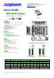

SPS-060 (3.3V, 5V) / SPS-060P (3.3V, 5V)
SPS-070 / SPS-070P / SPS-075
SDS-060
Series User’s Menu
Please read this user's guide carefully before setup.
Input:
1. Input range:
SPS-060 (3.3V, 5V) / SPS-060P (3.3V, 5V) / SPS-070 / SPS-070P:
Universal full range AC 85V ~ 264V or DC 120V ~ 375V
SPS-075: 85V ~ 132V or 170 ~ 264V select by switch.
SDS-060A: 9.5 ~ 18VDC / SDS-060B: 18 ~ 36VDC / SDS-060C: 36 ~ 72VDC
2. Inrush current: When turn on input power, there is peak current (inrush current)
running through filter capacitor. During operating, it is important not to turn off
power SW and then immediately turn on it again, otherwise, it may cut power
supply’s life.
In general, inrush current could be several to tens times of the normal current. It is
important to make sure input wiring, fuse and power SW are able to carry inrush
current.
3. For input specification, please refer to the label on the product or visit
www.sunpower.com.tw
for newly update data.
Output:
1. The output voltage adjustable range is ±10% of rated output voltage. As output
power is V
0
x A
0
, when adjusting V
0
to a higher value, should decrease A
0
as well,
ex.:
For SPS-060-05, the rated output voltage is 5V, max output current is 12A: If
adjusting output voltage to 5.5V, should decrease max output current to 10.9A as
well; and even if adjusting output voltage to 4.5V, max output should not be over
12A.
2. For output specification, please refer to the label on the product or visit
www.sunpower.com.tw
for newly update data.
Protection:
1. Short circuit protection: When short circuit occurs, power supply will shutdown.
After fault condition has been removed, it will recover automatically.
2. Over load protection: When over loaded, power supply will shutdown. After fault
condition has been removed, it will recover automatically.
3. Over voltage protection: When output voltage exceeds normal condition, power
supply will shutdown. After fault condition has been removed, it will recover
automatically.
4. Input polarity reverse protection: Dc input models only.
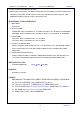
To Parallel Switching Power Supplies
a. Adjusting output voltage of each power supply to a same level, and then
serialize a diode after the positive pole of each power supply. The diode must be
equipped with a proper heat sink, and its current rating should be higher than
rated output current.
2
LOAD
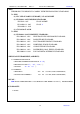
To Serialize Switching Power Supplies:
a. To up rise output voltage:
INPUT
Power Supply
(1)
INPUT
Power Supply
(2)
12V
12V
LOAD
b. To generate both positive and negative output voltage.
Power Supply
(1)
Power Supply
(2)
12V
12V
LOAD
LOAD
INPUT
INPUT
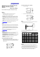
Wiring:
1. Output wiring must be thick and short enough to carry loading. The shorter and
thicker the wire, the less voltage it drops (less wire loss).
V+
Wire loss
Load
V-
2. Connecting the GND of power supply to system’s chassis with a short-thick wire
can reduce noise and prevent electric shock.
3. Reference data for wires:
Max. Load Current (A)
AWG
NO.
Area
(mm
2
)
Constitution
(Wire/mm)
Vol. Drop/1A
mV/m
U1007
(300V 80℃)
U1015
(600V 105℃)
30 0.051 7/0.102 358 0.12 ---
28 0.081 7/0.127 222 0.15 0.2
26 0.129 7/0.16 140 0.35 0.5
24 0.205 11/0.16 88.9 0.7 1.0
22 0.326 17/0.16 57.5 1.4 2.0
20 0.517 26/0.16 37.6 2.8 4.0
18 0.823 43/0.16 22.8 4.2 6.0
16 1.309 54/0.18 14.9 5.6 8.0
14 2.081 41/0.26 9.5 --- 12.0
12 3.309 65/0.26 6.0 --- 22.0
10 5.262 104/0.26 3.8 --- 35.0
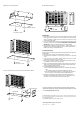
Mounting:
1. Each power supply is enclosed with a set of screws. It is suggested to use
enclosed screws to setup the power supply, otherwise, make sure its length must
not be too long (refer to drawing of next page) to cause electric short.
2. The input wiring should be separated from output wiring to avoid noise interfere.
3. When multiple power supplies operate together, be sure to keep proper distance
between power supply & power supply as well as power supply and the
environment for good air convection. Add cooling fans if needed.