
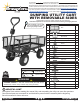
Instructions / Assembly

Page 4 / 5LW-DUCL 10/2020
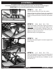
STEP 9
G: 2 U: 2 W: 2
Ensuring the valve stem is facing outward, place
Wheel (G) onto Rear Axle (N). Place 1x Washer (W)
onto the rear axle and secure using 1x Cotter Pin (U).
Repeat on the opposite side.
Ensuring the valve stem is facing outward, place
Wheel (G) onto Front Axle Brace (L). Place 1x Washer
(X) onto the front axle and hand-tighten 1x Lock Nut
(S). Repeat on the opposite side.
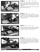
Flip the cart upright.
of the cart bed, connect Front Panel (C), Back Panel
(D), and 2x Side Panel (B) using Fence Assembly
Pins (V).
NOTE: the front panel must be installed above the
yoke and release handle, as shown.
STEP 10 B: 1 C: 1 D: 2 V: 8
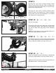
STEP 11 F: 1 M: 1 O: 1 Y: 1 T: 1
Place Hand Coupler (F) over the narrow end of Handle
(M). Connect the narrow end of the handle to the yoke
using 1x Bolt (O), Washer (Y) and Lock Nut (T).
Slide the D-handle over the U-Bracket on Handle (M)
and secure with Handle Pin (R) and Cotter Pin (U).
Tighten all lock nuts using a socket wrench and/or an
adjustable wrench. Tools not included.
STEP 12 R: 1 U: 1
BACK FRONT
G: 2 X: 2 S: 2
IMPORTANT: Lock nuts must be installed with the nylon insert on the outside. Tools must be used to
fully tighten lock nuts, failure to properly tighten the lock nuts may result in product malfunction or personal injury.