
Installation Guide

Make sure the power is turned off at the source to
the junction box.
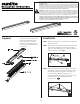
You are able to see a full layout
fixture, this will allow you to
access the LED’s or the LED
drivers. this component layout
will help on the installation of
this fixtures.
STEP 1.
Gently press housing base (B) near one end of the
fixture while pulling them the metal part of the
LED cover assembly (A) so that housing separates
at the seam as show. see Fig 1.
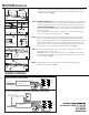
STEP 2.
Installation
Layeout
LED STRIP LIGHT FIXTURE | 85550, 85551, 85552, 85553
Please read and understand this entire manual before attempting to assemble, operate or
install the product.
WARNING: Avoid fire or electric shock. This product must be installed in accordance with the
applicable installation code by a person familiar with the construction and operation of the
product and the hazards involved. Before installing the fixture, ensure that all parts are present
and same as the part list. If any part is missing or damaged, do not attempt to assemble, install,
or operate this fixture. DO NOT REMOVE OR ATTEMPT TO REMOVE LEDs.
CAUTION: Turn off the power at fuse or circuit breaker box before installation and maintenance
to avoid electric shock. Select suitable location that can support the weight of the fixture.This
fixture requires a 120-277Volt AC power source. Fixture must be installed according to Nation-
al Electric Code and local building codes. Compatible with most wall based 0-10V dimmers.
Ambient operating temperature -20°C - 55°C (-4°F - 131°F). Suitable for Damp locations.
This device complies with part 15 of the FCC Rules. Operation is subject to the following two
conditions: (1) this device may not cause harmful inference, and (2) this device must accept
any inference received, including that may cause undesired operation.
Retain these instructions for future maintenance reference.
Set aside the LED cover assembly(A), and set the
housing base (B) on a firm surface with the back
side facing up. Determing which knockout will
be used to align with the wiring from the
mounting surface and using a screwdriver, punch
out the knockout hole and dispose of the
knockout. see Fig 2.
STEP 3.
2