RFID RF Module User’s Guide Model Number: SLF-10100 Model Name: RF Module v4.0 Edition version: 1.0 Date: 2006.11.
Regulatory Approvals FCC Statement This equipment has been tested and found to comply with the limits for a Class B digital device, pursuant to Part 15 of the FCC Rules. These limits are designed to provide reasonable protection against harmful interference in a residential installation. This equipment generates, uses and can radiate radio frequency energy and, if not installed and used in accordance with the instructions, may cause harmful interference to radio communications.
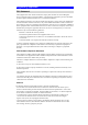
Index No. Item Page 1 Hardware 03 2 Software Operation 06 3 How to Contact Us 17 4 5 6 7 Notice: In order to avoid misuse or any unexpected damage, please read this guide first. This device complies with Part 15 of FCC Rules.
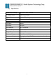
1. Hardware (1) Pin Description Pin No.
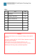
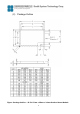
(2) Package Outline Figure: Package Outline – 42 Pin 37mm x 25mm x 3.
(3) Specification Power Supply Voltage DC 4.5V ~ 6.5V RF Output Power 100 mW (Contact) Trigger Mode Active & Passive LED Lamp Power on & Read TAG(Pin Output) Interface RS-232(TTL Level) Pin Output 44 Pin PCB Layer 4 Layer Outer Antenna U.FL Connector Operation Temperature 0 C ~ 45 C Storage Temperature 0 C ~ 60 C Frequency Range 2.40 GHz ~ 2.483 GHz Environment Requirement Storing Humidity 5-85%RH(no condensation allowed) Dimensions 37 x 25 x 2.
2.
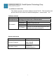
(3) Software introduction This software program can build a database include TAG ID、TAG information and picture.It can be use to demo for material management、access control… etc. Software contents Item Description Development tool Microsoft Visual Studio 2005 Traditional Edition DemoDTR.exe Main program File contents Sunlitrfid.dll Dynamic Link Library file Database.
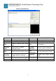
Main Program Window Item Description Item Description Port Name Show Device Comport Save Save registered database Open/Close Open & Close Device Comport Clear Clear text of Message window Find Finding Comport when device Exit add Exit program Operation Mode Select Active or Passive Operation mode Tag Data Base List Display registered database Mute Disable & Enable reading sound Tag Information Edit information about Tag ID Read Tag Trigger reader to scan tag Read Tag ID Display Ta
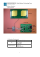
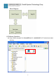
Block Diagram (4) Software Operation (a) Copy software program files “DemoDTR.exe” & “sunlitrfid.dll” to PC and store at same directory.
(b) Connect RS-232 cable & DC 5V power adaptor to reader. (c) Double click file “DemoDTR.exe” to open the demo program window. (d) Choose “Port Name” , from what the Device connected comport of PC.
(e) When device was opened, then Open item will change to Close (f)Create a data base. Set operation mode to “Passive” ※Passive: Click “Read Tag” once and reader will scan once.
Click “Read Tag” to read Tag and Tag ID will show on Message window Tag ID Choose picture that you want to correct with Tag ID. Click “Picture” to select picture. ※This is based on the pictures that each User’s PC has, we do not provide any picture. User needs to put pictures in PC in advance.
After choose picture, edit Tag Information and click “Save”. 1 2 When click Save, you will see the register data on “Tag DataBase List” window. It means data registered successfully.
(g) Delete data base Click data base you want to delete and click “Delete” 2 1 3 When delete the register data, you will see the “Tag DataBase List” window is no data.
(h) Clear information When you click “Clear”, the message of “Message” & “Tag DataBase List” window will be clear. (i) Set operation mode to “Active” 1 ※Active: Click “Read Tag” once and reader will scan continuously.
3 2 Click “Read Tag” once, Reader will read tag ID continuously until you remove tag.
(j) Set Operation mode to “Mute“ Check “Mute” box to enable mute function. 3. How to Contact Us For further information or in case of difficulties please contact Sunlit System Technology Corp. www.sunlitcorp.com 8F, No.19, Lane 120, Sec.1, Neihu Rd., Taipei Taiwan 114 R.O.C. webmaster@sunlitcorp.