
Instructions / Assembly

16
ASSEMBLY INSTRUCTIONS
8
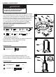
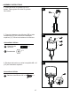
8. WARNING:Remove protective cover before
assembling.
Note: If necessary for proper alignment of reflector
sections, loosen each bolt prior to further assembly
and retighten after sections are aligned.
B
A
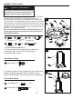
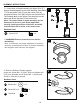
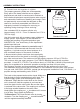
7-1. Insert hose of Head Assembly into Upper Pole (F).
Secure Head Assembly to pole with Stainless Steel Bolts.
7-2.Put the Upper Pole ( F) onto the Lower Pole (H),
using 4pcs Screw 3/16” (KK) to firmly secure 2pcs Pole.
The warning label on the Upper Pole should be on the
same side as the flat plate of the Lower Pole.
Note: The control knob on head assembly should
be above the decal on pole. When applicable,
visually checking portions of the hose assembly
located within the confines of the heater post.
7
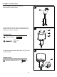
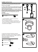
Hardware Used
GG
HH
II
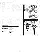
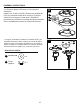
9. Slide two Reflector Panels together.
Insert one Screw M6 x 10 (HH). Slide one Washer Φ6
(GG) over threaded end of Screw M6 x 10 (HH) and
screw on Cap Nut (II) loosely.
x 9
x 9
x 9
Screw M6 x 10
Washer Φ6
Cap Nuts
II
GG
HH
9
F
CC
KK
H
Hard
ware Used
KK
x 4
Screw 3/16”