
User Manual

81
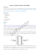
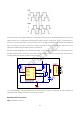
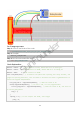
Schematic diagram:
Principle: Plug the power supply module in breadboard, and insert the jumper cap to pin of
5V, then it will output voltage of 5V. Connect pin 1 of L293D to B27, and set it as high lev el.
Connect pin2 to B18, and pin7 to B27, then set one pin high, while the other low. Thus you
can change the motor’s rotation direction.
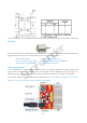
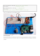
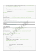
Experimental Procedures
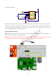
Step 1: Build the circuit. Since the pow er supply module and T-cable are incompatible, we
will not use the T-Cable in this experiment.
Note: The power module can apply a 9V battery with the 9V Battery Buckle in the kit. I nsert
the jumper cap of the power module into the 5V bus strips of the breadboard.
0
SunFounder