
User Manual

68
the load short circuit occurs, it won't affect the control board, thus realizing good electrical
isolation.
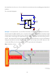
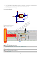
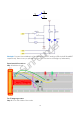
The schematic diagram:
Principle: In this experiment, use an LED as the load connected to the NPN phototransistor.
Connect pin 2 of 4N35 to pin B17, pin 1 connects a 1K current-limiting resistor and then a 3.3V.
Connect pin 4 to GND, and pin 5 to the cathode of the LED. Then hook the anode of the LED
to 3.3V after connecting with a 220 Ohm resistor. When in program, a LOW lev el is given to
pin B17, the infrared LED w ill emit infrared rays. Then the phototransistor receiv es infrared rays
and gets electrified, and the LED cathode is LOW, thus turning on the LED. Also you can
control the LED by circuits only – connect pin 2 to ground and it will brighten.
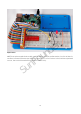
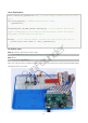
Step 1: Build the circuit
SunFounder