
User Manual


107
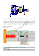
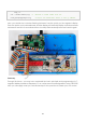
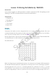
Step 3: Insert the dot matrix onto the breadboard. The 74HC595 on the right side is to control
columns of the matrix. See the table below for the mapping. Therefore, Q0-Q7 pins of the
74HC595 are mapped with pin 13, 3, 4, 10, 6, 11, 15, and 16 respectively.
COL
1
2
3
4
5
6
7
8
Pin No.
13
3
4
10
6
11
15
16
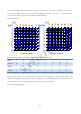
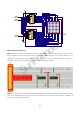
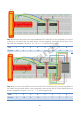
Step 4: Now connect the ROWs of the dot matrix. The 74HC595 on the left controls ROW of
the matrix. See the table below for the mapping. We can see, Q0-Q7 of the 74HC595 on the
left are mapped w ith pin 9, 14, 8, 12, 1, 7, 2, and 5 respectively.
ROW
1
2
3
4
5
6
7
8
Pin No.
9
14
8
12
1
7
2
5
SunFounder