
User Manual


105
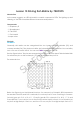
you want to light up the whole first column, for CA, set pin 13 as Low and ROW 9, 14, 8, 12, 1,
7, 2, and 5 as High, w hen for CC, set pin 13 as High and ROW 9, 14, 8, 12, 1, 7, 2, and 5 as Low.
Consider the follow ing figures for better understanding.
The internal view:
Common Anode Common Cathode
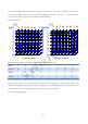
Pin numbering corresponding to the abov e rows and columns:
COL
1
2
3
4
5
6
7
8
Pin No.
13
3
4
10
6
11
15
16
ROW
1
2
3
4
5
6
7
8
Pin No.
9
14
8
12
1
7
2
5
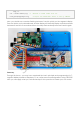
In this experiment, a CA dot matrix is used. You can see the label ends with "BS". The wiring
and code are done for the CA matrix. Therefore, if you happen to have a CC matrix, you
need to change the wiring and code. I n addition, two 74HC595 chips are used here. One is
to control the rows of the dot matrix while the other, the columns.
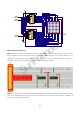
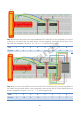
The schematic diagram
SunFounder