Preface About SunFounder SunFounder is a technology company focused on Raspberry Pi and Arduino open source community dev elopment. Committed to the promotion of open source culture, w e striv e to bring the fun of electronics making to people all around the w orld and enable ev eryone to be a maker. Our products include learning kits, dev elopment boards, robots, sensor modules and dev elopment tools. I n addition to high quality products, SunFounder also offers v ideo tutorials to help your ow n project.
Contents Components List .................................................................................................................................. 1 Components Introduction.................................................................................................................. 8 Resistor ............................................................................................................................................... 8 Potentiometer..............................................
Lesson 4 Breathing LED...................................................................................................................... 50 Lesson 5 RGB LED ............................................................................................................................... 54 Lesson 6 Buzzer ................................................................................................................................... 58 Lesson 7 Relay ......................................................
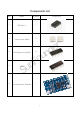
Components List No.
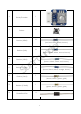
6 7 8 9 1 Rotary Encoder 5 Button 8 Resistor (220Ω) r e (red, red, black, black, brow n) 8 Resistor (1kΩ) u o F d n (brow n, black, black, brow n, brow n) 10 11 12 13 14 Resistor (10kΩ) n u S Resistor (100kΩ) Resistor (1MΩ) Resistor (5.
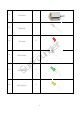
15 16 17 18 1 Sw itch 20 1 Pow er Supply Module LCD1602 u o F n u S 19 1 Potentiometer (50k) Dot Matrix Display (8*8) 7-Segment Display 1 1 2 3 d n r e
21 22 23 24 25 26 1 DC Motor 1 RGB LED 8 LED (red) u o F 4 LED (w hite) S n u LED (green) LED (yellow ) 4 4 4 d n r e
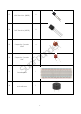
27 28 29 2 NPN Transistor (S8050) 2 PNP Transistor (S8550) Capacitor Ceramic 4 100nF 30 10nF 31 32 u o F Capacitor Ceramic n u S Breadboard Activ e Buzzer 4 1 1 5 d n r e
33 34 35 1 Relay 1 Fan Male-to-Male 65 Jumper Wire 36 n u Female-to-Male Dupont Wire S 37 u o F 5-Pin Anti-rev erse Cable 20 2 6 d n r e
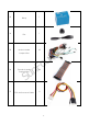
38 1 9V Battery Buckle 39 M3*10 Screw 2 40 M2.5*6 Screw 4 41 M3*6 Screw 6 42 1 RAB Holder n u u o F 43 T-Extension Board 44 40-Pin GPI O Cable S d n r e 1 1 Notes: After unpacking, please check that the number of components is correct and that all components are in good condition.
Components Introduction Resistor Resistor is an electronic element that can limit the branch current. A fixed resistor is one whose resistance cannot be changed, w hen that of a potentiometer or v ariable resistor can be adjusted. The resistors in this kit are fixed ones. I t is essential in the circuit to protect the connected components. Figure (a) below show s a 220Ω resistor. Ω is the unit of resistance and the larger includes KΩ, MΩ, etc.
As show n in the card, each color stands for a number. Black Brown Red Orange Yellow 0 1 2 3 4 Green Blue Violet Grey White Gold Silv er 5 6 7 8 9 0.1 0.01 The 4- and 5-band resistors are frequently used, on w hich there are 4 and 5 chromatic bands. Let’s see how to read the resistance v alue of a 5-band resistor as show n below . Normally, w hen you get a resistor, you may find it hard to decide w hich end to start for reading the color.
Read the resistance of the abov e resistor from left to right. The v alue is 1(brow n) 0(block) x 10^5(green)=10x10^5Ω=10^6Ω=1MΩ and the permissible error is ±5%(gold) The resistance v alue of the resistor below is 5(green) 1(brow n) x 10^5(green) = 51 x 10^5 Ω = 5.1 x 10^6 Ω = 5.1 MΩ, and the permissible v alue is ±5% (gold). (h) You can also use a multimeter to measure the resistance v alue of these resistors to double check w hether you've read it correctly or not.
When the potentiometer is used as a rheostat, connect the middle pin and one of the other 2 pins in the circuit. Thus you can get a smoothly and continuously changed resistance value within the travel of the mov ing contact. 3. Serv ing as a current controller When the potentiometer acts as a current controller, the sliding contact terminal must be connected as one of the output terminals.
RGB LED An RGB LED is prov ided in this kit. RGB LEDs emit light in v arious colors. An RGB LED packages three LEDs of red, green, and blue into a transparent or semitransparent plastic shell. I t can display v arious colors by changing the input v oltage of the three pins and superimpose them, w hich, according to statistics, can create 16,777,216 different colors. RGB LEDs can be categorized into common anode and common cathode ones. I n this experiment, the latter is used.
comes the green and the blue one. Therefore, you may need to add a current limiting resistor w ith different resistances to the three pins for these colors. Jumper Wires Wires that connect tw o terminals are called jumper w ires. There are v arious kinds of jumper w ires. Here w e focus on those used in breadboard. Among others, they are used to transfer electrical signals from anyw here on the breadboard to the input/output pins of a microcontroller.
soldering up your circuit. Therefore, in lots of experiments, it is often used as a hub to connect tw o or more dev ices. Normally, there are tw o types of breadboard: full+ and half+. You can tell their difference from the names. A half+ breadboard is half the size of a full+ one and their functions are the same. Here take the full+ breadboard. (s) Full+ u o F d n r e n u S (t) Half+ This is the internal structure of a full+ breadboard.
(u) I nternal structure of the full+ Now let’s make some simple experiment w ith the breadboard. Turn on an LED as show n in the figure below . You can hav e a try and the LED w ill light up. The breadboard makes it possible for you to plug and pull components at any time w ithout w elding, w hich is v ery conv enient for tests.
Get Started Preparation 1. Prepare a MicroSD/TF card of no less than 8GB, a 5V 2A DC pow er adapter w ith a MicroUSB port, and a netw ork cable (to connect your router and Raspberry Pi, or plug in the USB Wi-Fi adapter directly if you hav e one). 2. Dow nload the image for the Raspbian system onto your computer. Refer to instructions through DOWNLOADS->RASPBIAN on the official w ebsite raspberrypi.org: https://www.raspberrypi.org/documentation/installation/installing-images/README.md.
I f the monitor displays colored texts w ith a black background after booting, and that is in console. You can just use this as a terminal (but not recommend for beginners), or change the option for automatically loading a graphic user interface (GUI ). To activ ate GUI , you can type in startx w ith the keyboard and press Enter, and to alw ays boot up to GUI , type in sudo raspi-config and go through Boot Options > Desktop/Desk Autologin, and reboot.
4. Then a terminal w ill pop up as follow s: Here’s the console w e talk about before. u o F Using Console Only d n r e There are sev eral w ays to use the console only and they can be div ided into mainly two ways: using directly and remotely. n u A. Directly A screen is needed w hen you use the console directly. S 1. Preparations: a screen monitor, an HDMI cable (if your monitor only support VGA, use a VGA-HDMI conv erter), a USB keyboard and a netw ork cable or a USB Wi-Fi dongle.
u o F Type in ssh pi@ d n r e – ssh is the tool for remote login; pi, the user name, and as the name suggests, your RPi's I P address. For example: n u ssh pi@192.168.0.1 Press Enter to confirm. S I f you get a prompt that no ssh is found, you need to install a ssh tool like Ubuntu and Debian by yourself: sudo apt-get install ssh For other platforms, please contact your supplier. For Windows users, you may use a ssh tool to log into Raspberry Pi remotely, like PuTTY. 1.
4. Enter the I P address of the RPi you just got in the textbox under Host Name (or I P address) and 22 under Port (by default it is 22) u o F d n r e n u S 5. Click Open. Note that w hen you first log in to the Raspberry Pi w ith the I P address, you'll be prompted w ith a security reminder. Just click Yes. When the PuTTY w indow prompts login as: type in the user name of the RPi: pi, and you hav en't changed it).
Note: w hen you're typing the passw ord in, the w indow show s nothing just null, but you're in fact is typing things in. So just focus on typing it right and press Enter. After you log in the RPi successfully, the w indow will display as follows. r e Now , no matter w hat method you take, you can get in the console of your Raspberry Pi.
Introduction to Raspberry Pi RAB Holder RAB Holder is a basic but indispensable component for your experiment. I t makes your experiment easier and can be used for fixing a bread board, an Arduino board like Uno board or Mega2560, or a Raspberry Pi board. Before starting the experiment, you need to fix the Raspberry Pi and the breadboard on the RAB Holder first. Remov e the sticker from the back of the breadboard first, and fix the breadboard on the RAB Holder.
Then place the Raspberry Pi in the holder, fasten it w ith M2.5x5 screw s. Since it may be a little difficult to fasten it, be careful to operate. u o F d n r e Pay attention to the direction w hen plugging in the 40-pin GPI O Cable into the Raspberry Pi pins. The black w ire at the edge should be close to the TF card slot.
Raspberry Pi r e A Raspberry Pi is an indispensable component for the kit, the control dev ice. But it is not included in the kit and you need to prepare one yourself. d n The Raspberry Pi is a kind of minicomputer for users like amateurs, teachers, students and small businesses, etc. With a pre-installed Linux system, it is credit card-sized and equipped u o F w ith an ARM architecture processor, w hose operational performance is similar to that of smart phone.
actual pins are corresponding to the Physical on the right. There are 40 pins in total from left to right. The columns near Physical are the V (v oltage), Mode (I nput or Output), Name (original name), w Pi (w iringPi, C language based on), BCM (Python based on) of the pins. 1 3 5 7 9 11 13 15 17 19 21 23 25 27 29 31 33 35 37 39 u o F d n r e Besides the original name of the pins, there are other three w ays of naming including physical, w iringPi and BCM.
This is our 40-pin GPI O Extension Board and GPI O cable for Raspberry Pi model B+, 2 model B and 3 model. r e For your better understanding of ev ery pins, w e hav e draw n a table for you to know the Name, BCM and w iring pi of each pin. u o F d n n u S 26-pin GPIO Extension Board 26-pin GPI O Extension Board and GPI O cable for Raspberry Pi model B and Raspberry Pi model A.
Also, w e hav e drawn a table of the corresponding BCM, w iringPi and Name of each pins.
GPIO Libraries WiringPi Introduction WiringPi is a GPI O library for C applied to the Raspberry Pi. I t complies w ith GUN Lv 3. The functions in w iringPi are similar to those in the w iring system of Arduino. They enable the users familiar w ith Arduino to use w iringPi more easily. Now the Raspbian Jessie 2016-05-27 has w iringPi pre-installed, you can use it directly. Test w hether wiringPi is installed or not.
u o F RPi.GPIO d n r e I f you are a Python user, you can program GPI Os w ith API prov ided by RPi.GPIO and use BCM numbering method to control the GPI Os of Raspberry Pi. Please note that it differs from the n u w ay that using w iringPi numbering method to control the GPI O on a Raspberr y Pi in C language. Introduction S RPi.GPI O is a module to control Raspberry Pi GPI O channels. This package prov ides a class to control the GPI O on a Raspberry Pi.
I f no error prompts, it means RPi.GPI O is installed. Then, type in RPi.GPIO.VERSION I f it show s its v ersion like above, your Pi is ready to go! So in this kit, please note that the example code is ONLY test on Raspbian.
Download the Code We prov ide tw o methods for download: Method 1: Use git clone (Recommended) Log into Raspberry Pi’s console, just as prev iously shown. Change directory to /home/pi cd /home/pi/ Note: cd to change to the intended directory from the current path. Informally, here is to go to the path /home/pi/. Clone the repository from GitHub r e git clone https://github.com/sunfounder/SunFounder_Super_Kit_V3.0_for_Raspberry_Pi.
Lesson 1 Blinking LED Introduction I n this lesson, w e w ill learn how to program Raspberry Pi to make an LED blink. You can play numerous tricks w ith an LED as you w ant. Now get to start and you w ill enjoy the fun of DI Y at once! Components - 1 * Raspberry Pi - 1 * Breadboard - 1 * T-Extension Board - 1 * 40-Pin Cable - 1 * LED - 1 * Resistor (220Ω) - Jumper w ires Principle d n r e I n this experiment, connect a 220Ω resistor to the anode (the long pin of the LED), then the u o F resistor to 3.
For C language users: Step 2: Go to the folder of the code. If you use a monitor, you're recommended to take the following steps. Go to /home/pi/ and find the folder SunFounder_Super_Kit_V3.0_for_Raspberry_Pi . Find C in the folder, right-click on it and select Open in Terminal. u o F d n r e Then a w indow w ill pop up as show n below . So now you'v e entered the path of the code n u 01_blinkLed.
I n either w ay, you now are in the folder C. The subsequent procedures under the tw o methods are the same. Let's mov e on. Step 3: Compile the Code gcc 01_blinkLed.c -o 01_blinkLed -lwiringPi d n r e Note: gcc is GNU Compiler Collection. Here, it functions like compiling the C language file 01_blinkLed.c and outputting an executable file 01_blinkLed. In the command, -o means u o F outputting and -lwiringPi is to load the library wiringPi (l is short for library).
I f you w ant to v iew the code 01_blinkLed.c, press Ctrl + C to stop running the code. Then type the follow ing command to open it: nano 01_blinkLed.c r e Note: nano is a text editor tool. The command is to open the code file 01_edblinkLed.c by this tool. u o F d n n u S Code Explanation #include //The hardware drive library designed for the C language of Raspberry Pi. Adding this library is convenient for hardware initialization, I/O ports, PWM outputs, etc. #include
#define LedPin 0 // Pin B17 of the T_Extension Board is corresponding to the pin0 in wiringPi, namely, GPIO 0 of the raspberry Pi. Assign GPIO 0 to LedPin, LedPin represents GPIO 0 in the code later. pinMode(LedPin, OUTPUT)// Set LedPin as output to write value to it. digitalWrite(LedPin, LOW)// Set GPIO0 as 0V (low level). Since the cathode of LED is connected to GPIO0, thus the LED will light up if GPIO0 is set low. On the contrary, set GPIO0 as high level, digitalWrite (LedPin, HIGH): LED will go out.
r e To stop it from running, just click the X button on the top right to close it and then you'll back to the code details. I f you modify the code, before clicking Run Module (F5) you need to sav e it first. Then you can see the results. d n If you want to log into the Raspberry Pi remotely, type in the command: u o F cd /home/pi/SunFounder_Super_Kit_V3.0_for_Raspberry_Pi /Python Run the code: sudo python 01_blinkLed.py n u Note: Here sudo – superuser do, and python means to run the file by Python.
Code Explanation #!/usr/bin/env python: d n r e When the system detects this, it will search the installation path of python in the env u o F setting, then call the corresponding interpreter to complete the operation. It’s to prevent the user not installing the python onto the /usr/bin default path. import RPi.GPIO as GPIO # import RPI.GPIO package, thus python code control GPIO easily n u with it. import time # import time package, for time delay function in the following program.
# delay 0.5 second, which is equals to the delay in C language, using second as the unit, time.sleep(0.5) print 'LED OFF...' # Turn off LED GPIO.output(LedPin, GPIO.HIGH) time.sleep(0.5) # Define a destroy function for clean up everything after the script finished def destroy(): # Turn off LED GPIO.output(LedPin, GPIO.HIGH) # Release resource GPIO.
Then press Enter to exit. Type in nano 01_blinkLed.py again to see the effect after the change. Run the code to make it w ork. I t will be like below: Further Exploration u o F d n r e I f you w ant the LED to speed up the blinking, just change the delay time. For example, change the time to delay (200) (for C) or time.sleep(0.2) (for python) in the program, recompile and run, and then you w ill see the LED blink faster.
Lesson 2 Controlling an LED by a Button Introduction I n this lesson, w e will learn how to turn an LED on or off by a button. Components - 1 * Raspberry Pi - 1 * Breadboard - 1 * LED - 1 * Button - 1 * Resistor (220Ω) - Jumper w ires - 1 * T-Extension Board - 1 * 40-Pin Cable Principle Button d n r e Buttons are a common component used to control electronic dev ices. They are usually used u o F as sw itches to connect or disconnect circuits.
When the button is pressed, the 4 pins are connected, thus closing the circuit. Use a normally open button as the input of Raspberry Pi, the detailed connection is as shown in the schematic diagram below . When the button is pressed, the B18 w ill turn into low lev el (0V). We can detect the state of the B18 through programming. That is, if the B18 turns into low lev el, it means the button is pressed. You can run the corresponding code w hen the button is pressed, and then the LED w ill light up.
For C language users: Step 2: Open the code file: cd /home/pi/SunFounder_Super_Kit_V3.0_for_Raspberry_Pi/C Note: Change directory to the path of the code in this experiment via cd. Step 3: Compile the Code gcc 02_buttonControlLed.c -o 02_buttonControlLed -lwiringPi or make 02_buttonControlLed Step 4: Run the executable file abov e sudo ./02_buttonControlLed Step 5: Check the code nano 02_buttonControlLed.
digitalWrite (LedPin, HIGH) in while: close the LED. if (digitalRead (ButtonPin) == 0: check whether the button has been pressed. Execute digitalWrite(LedPin, LOW) when pressed to light up LED. Press Ctrl+X to exit, if you hav e modified the code, there w ill be a prompt asking w hether to sav e the changes or not. Type in Y (sav e) or N (don’t sav e). Then press Enter to exit. Repeat Step 3 and Step 4 to see the effect after modifying.
u o F Summary d n r e Through this experiment, you hav e learnt how to control the GPI Os of the Raspberry Pi by programming.
Lesson 3 Flowing LED Lights Introduction I n this lesson, w e w ill learn how to make eight LEDs blink in v arious effects as you w ant based on Raspberry Pi.
For C language users: Step 2: Open the code file cd /home/pi/SunFounder_Super_Kit_V3.0_for_Raspberry_Pi /C r e Note: Use the cd command to sw itch to the code path of this experiment. Step 3: Compile the Code gcc 03_8Led.c -o 03_8Led -lwiringPi or u o F make 03_8Led d n Note: gcc is a linux command w hich can realize compiling and generating the C language program file 03_8Led.c to the executable file 03_8Led.
Code Explanation void Led_on(int channel): This is a subfunction with a formal parameter int channel for importing the numbers of the controlled pins. Its function body is digitalWrite(channel, LOW); Set the I/O port of channel as low level(0V), the LED on this port lights up. void led_off(int channel) is to turn off the LED. Setting function simplifies the input for the repeated content.
for pin in LedPins # Assign the element in pins list to pin variable one by one. In GPIO.setup (pin, GPIO.OUT), set the pins in list as output one by one. GPIO.output(pin, GPIO.LOW) # Set each element in the pins list as low level to light up the LEDs leds[LedPins.index(pin)] = 0 # Show which LED is on time.sleep(0.1) # wait for 0.1s GPIO.output(pin, GPIO.HIGH)) # After delaying, set it as high level to light up or turn off the LED. leds[LedPins.
Lesson 4 Breathing LED Introduction I n this lesson, w e w ill try something interesting – gradually increase and decrease the luminance of an LED w ith PWM, just like breathing. So w e giv e it a magical name - Breathing LED. Components - 1 * Raspberry Pi - 1 * Breadboard - 1 * LED - 1 * Resistor (220Ω) - Jumper w ires - 1 * T-Extension Board - 1 * 40-Pin Cable u o F Principle PWM d n r e Pulse Width Modulation, or PWM, is a technique for getting analog results w ith digital means.
r e I n this experiment, w e use this technology to make the LED brighten and dim slow ly so it looks like our breath. Experimental Procedures Step 1: Build the circuit u o F d n S n u For C language users: Step 2: Open the code file cd /home/pi/SunFounder_Super_Kit_V3.
Step 3: Compile the Code make 04_breathLed Step 4: Run the executable file abov e sudo ./04_breathLed Code Explanation pinMode(LedPin, PWM_OUTPUT); // Set the I/O as pwn output for(i=0;i<1024;i++){ // i,as the value of pwm, increases progressively during 0-1024. pwmWrite(LedPin, i); // Write i into the LEDPin delay(2); // wait for 2ms, interval time between the changes indicates the speed of breathing.
pLed.ChangeDutyCycle(dc) # ChangeDutyCycle() function in pLED output pulse width 0~100% according to the variable dc. print " ++ Duty cycle: %s"%dc # print information time.sleep(delay) # it will delay after changing the pulse width for each time, this parameter can be modified to change the LED’s lighting and dimming speed. time.sleep(1) # decrease duty cycle from 100 to 0 for dc in range(100, -1, -step): # the luminance of the LED decreases with each cycle. # Change duty cycle to dc pLED.
Lesson 5 RGB LED Introduction Prev iously w e'v e used the PWM technology to control an LED brighten and dim. I n this lesson, w e w ill use it to control an RGB LED to flash v arious kinds of colors. Components - 1 * Raspberry Pi - 1 * Breadboard - 1 * RGB LED - 3 * Resistor (220Ω) - Sev eral jumper w ires Principle r e I n this experiment, w e w ill use a RGB. For details of RGB, please refer to the introduction of RGB LED in Components Introduction.
Step 1: Build the circuit For C language users: Step 2: Open the code file d n cd /home/pi/SunFounder_Super_Kit_V3.0_for_Raspberry_Pi/C Step 3: Compile the Code u o F make 05_rgb Step 4: Run the executable file abov e sudo ./05_rgb r e n u Code Explanation #include // library used for realizing the pwm function of the software. void ledInit(void){ pwm. S // define function used for initializing I/O port to output for // LedPinX refers to one pin.
softPwmWrite(LedPinBlue, b_val); } ledColorSet(0xff,0x00,0x00); // red calls the function defined before. Write oxff into LedPinRed and ox00 into LedPinGreen and LedPinBlue. Only the Red LED lights up after running this code. If you want to light up LEDs in other colors, just modify the parameters. For Python users: Step 2: Open the code file cd /home/pi/SunFounder_Super_Kit_V3.0_for_Raspberry_Pi /Python Step 3: Run sudo python 05_rgb.
R_val = MAP(R_val, 0, 255, 0, 100) # use map function to map the R,G,B value among 0~255 into PWM value among 0-100. G_val = MAP(G_val, 0, 255, 0, 100) B_val = MAP(B_val, 0, 255, 0, 100) p_R.ChangeDutyCycle(R_val) # Assign the mapped duty cycle value to the corresponding PWM channel to change the luminance. p_G.ChangeDutyCycle(G_val) p_B.
Lesson 6 Buzzer Introduction I n this lesson, w e will learn how to drive an active buzzer to beep w ith a PNP transistor. Components - 1 * Raspberry Pi - 1 * Breadboard - 1 * Buzzer (Activ e) - 1 * PNP transistor (8550) - 1 * Resistor (1KΩ) - Jumper w ires Principle Buzzer d n r e As a type of electronic buzzer w ith integrated structure, buzzers, w hich are supplied by DC pow er, are w idely used in computers, printers, photocopiers, alarms and other electronic products for v oice dev ices.
You can check the pins of the buzzer, the longer one is the anode and the shorter one is the cathode. Please don’t mix them up w hen connecting, otherw ise the buzzer w ill not make sound. Transistor The transistor is a semiconductor dev ice that controls current by current. I t functions by amplifying w eak signal to larger amplitude signal and is also used as a non-contact sw itch. A transistor is a three-layer structure composed of P-type or N-type semiconductors. They form the three regions internally.
When a High lev el signal goes through an NPN transistor, it is energized. But a PNP one needs a Low lev el signal to manage it. Both types of transistor are frequently used for contactless sw itches, just like in this experiment. The schematic diagram: u o F d n r e Principle: I n this experiment, an activ e buzzer, a PNP transistor and a 1k resistor are used n u betw een the base of the transistor and GPI O to protect the transistor .
For C language users: Step 2: Open the code file d n cd /home/pi/SunFounder_Super_Kit_V3.0_for_Raspberry_Pi /C Step 3: Compile the Code make 06_beep u o F Step 4: Run the executable file abov e. sudo ./06_beep Code Explanation r e n u digitalWrite(BeepPin, LOW); // We use an active buzzer in this experiment, so it will make sound automatically when connecting to the direct current. This sketch is to set S the I/O port as low level (0V), thus to manage the transistor and make the buzzer beep.
time.sleep(0.1) Now , you should hear the buzzer make sounds. u o F n u Further Exploration d n r e I f you hav e a passiv e buzzer in hand, you can replace the activ e buzzer w ith it. Now you can S make a buzzer sound like “do re mi fa so la si do” w ith just some basic know ledge of programming.
Lesson 7 Relay Introduction As w e know relay is a dev ice w hich is used to prov ide connection betw een tw o or more points or dev ice in response to the input signal applied. I n another w ords relay prov ide isolation betw een the controller and the dev ice as w e know dev ices may work on AC as well as on DC. How ev er, they receiv e signals from microcontroller w hich w orks on DC hence we require a relay to bridge the gap.
Working of Relay The w orking principle of relay is simple. When pow er is supplied to the relay, currents start flow ing through the control coil; as a result, the electromagnet starts energizing. Then the armature is attracted to the coil, pulling dow n the mov ing contact together thus connecting w ith the normally open contacts. So the circuit w ith the load is energized.
Step 1: Build the circuit For C language users: Step 2: Open the code file d n cd /home/pi/SunFounder_Super_Kit_V3.0_for_Raspberry_Pi/C u o F Step 3: Compile the Code make 07_relay Step 4: Run the executable file abov e n u sudo ./07_relay Code Explanation r e S digitalWrite(relayPin, LOW); // set the I/O port as low level (0V) to energize the transistor. The coil of the relay is powered and generate electromagnetic force, and the relay closes.
GPIO.output(relayPin, GPIO.LOW) # Set the pins of transistor as low level to actuate the relay. time.sleep(1) # wait for 1 second. Change the switching frequency of the relay by changing this parameter. Note: Relay is a kind of metal dome formed in mechanical structure. So its lifespan will be shortened under high-frequency using. GPIO.output(relayPin, GPIO.HIGH) # Set the pins of the transistor as low level to let the relay open. time.
Lesson 8 4N35 Introduction The 4N35 is an optocoupler for general purpose application. I t consists of gallium arsenide infrared LED and a silicon NPN phototransistor. When the input signal is applied to the LED in the input terminal, the LED lights up. After receiv ing the light signal, the light receiv er then conv erts it into electrical signal and outputs the signal directly or after amplifying it into a standard digital lev el.
the load short circuit occurs, it w on't affect the control board, thus realizing good electrical isolation. The schematic diagram: d n r e Principle: I n this experiment, use an LED as the load connected to the NPN phototransistor. Connect pin 2 of 4N35 to pin B17, pin 1 connects a 1K current-limiting resistor and then a 3.3V. Connect pin 4 to GND, and pin 5 to the cathode of the LED. Then hook the anode of the LED u o F to 3.3V after connecting w ith a 220 Ohm resistor.
For C language users: Step 2: Open the code file cd /home/pi/SunFounder_Super_Kit_V3.0_for_Raspberry_Pi/C Step 3: Compile the Code make 08_4N35 Step 4: Run the executable file abov e. sudo ./08_4N35 Code Explanation digitalWrite(_4N35Pin, LOW); // set the I/O port as low level (0V), thus the optocoupler is energized, and the pin connected to LED conducts to the 0V. Then the LED lights up. r e delay(500); // optocoupler is a kind of electronic device and there is no limitation on its on-off frequency.
u o F Exploration d n r e 4N35 is an optocoupler that usually used for driv ing relay as w ell as motor circuits. As there is no direct connection betw een the input and output, ev en if a short circuit at the output end n u occurs, the control board w ill not be burnt.
Lesson 9 Ne555 Introduction I f you ask anyone in the know to rank the most commonly and w idely used I C, the famous 555 time base I C w ould certainly be at the top of the list. The 555 – a mixed circuit composed of analog and digital circuits – integrates analogue and logical functions into an independent I C, and hence tremendously expands the application range of analog integrated circuits. The 555 is w idely used in v arious timers, pulse generators, and oscillators.
Pin 7 (DI SCHARGE): hav ing tw o states of suspension and ground connection also decided by input, and the output of the internal discharge tube; Pin 8 (VCC): the pow er supply; The schematic diagram Experimental Procedures Step 1: Build the circuit u o F d n n u S For C language users: Step 2: Go to the folder of the code. cd /home/pi/SunFounder_Super_Kit_V3.0_for_Raspberry_Pi /C Step 3: Compile make 09_ne555 Step 4: Run the executable file abov e. sudo .
Code Explanation static volatile int globalCounter = 0 ; // a static integer variable to store the pulse count void exInt0_ISR(void) { //GPIO0 interrupt service routine ++globalCounter; } wiringPiISR(Pin0, INT_EDGE_FALLING, &exInt0_ISR); // set an interrupt here and the signal is falling edge for Pin 0. When the interrupt happens, execute the function exInt0_ISR(), and the pulse count will add 1. while(1){ // if no interrupt happens, the pulse count will stay and just print it.
Code Explanation g_count = 0 # a global variable used to store the pulse count def count(ev=None): global g_count # Define a function to be run when an interrupt happens # this function will change the value of the global variable g_count, thus here we add global before it. g_count += 1 GPIO.add_event_detect(SigPin, GPIO.RISING, callback=count) # set an interrupt here and the interrupt signal is a rising edge for Pin Sig.
Lesson 10 Slide Switch Introduction I n this lesson, w e w ill learn how to use a Slide Sw itch. Usually, the slide sw itch is soldered on PCB as a pow er sw itch, but here w e need to insert it into the breadboard, thus it may not be tightened. And w e use it on the breadboard is to show its function.
u o F d n r e Principle: Connect the middle pin of the Slide Sw itch to B17, and tw o LEDs to pin B18 and B27 respectively. Then w hen you pull the slide, you can see the tw o LEDs light up alternately. Experimental Procedures Step 1: Build the circuit n u S For C language users: Step 2: Go to the folder of the code.
cd /home/pi/SunFounder_Super_Kit_V3.0_for_Raspberry_Pi /C Step 3: Compile make 10_slideSwitch Step 4: Run the executable file abov e. sudo .
GPIO.output(led2Pin, GPIO.LOW) GPIO.output(led1Pin, GPIO.HIGH) Now pull the slide, and you can see the tw o LEDs light up alternately.
Lesson 11 How to Drive a DC Motor Introduction I n this lesson, w e w ill learn to how to use L293D to driv e a DC motor and make it rotate clockw ise and counterclockw ise. Since the DC Motor needs a larger current, for safety purpose, here we use the Pow er Supply Module to supply motors.
I n this experiment, it just needs to driv e one motor, so here only half of the L293D w ill be used. DC Motor d n r e This is a 5V DC motor. I t w ill rotate w hen you giv e the tw o terminals of the copper sheet one high and one low level. For convenience, you can w eld the pins to it.
Schematic diagram: Principle: Plug the pow er supply module in breadboard, and insert the jumper cap to pin of 5V, then it w ill output v oltage of 5V. Connect pin 1 of L293D to B27, and set it as high lev el. Connect pin2 to B18, and pin7 to B27, then set one pin high, w hile the other low . Thus you can change the motor’s rotation direction. Experimental Procedures d n r e Step 1: Build the circuit.
For C language users: Step 2: Get into the folder of the code cd /home/pi/SunFounder_Super_Kit_V3.0_for_Raspberry_Pi /C Step 3: Compile make 11_motor Step 4: Run the executable file abov e. sudo .
GPIO.output(MotorPin2, GPIO.LOW) # Make the motor rotate clockwise time.sleep(5) # rotate for 5 seconds GPIO.output(MotorEnable, GPIO.LOW) time.sleep(5) # Stop the motor #wait for 5 seconds Code for motor counter-clockwise rotation is similar to sketch above Now , you should see the motor blade rotating. Further Exploration u o F d n r e S n u You can use buttons to control the clockw ise and counterclockw ise rotation of the motor blade based on the prev ious lessons.
Lesson 12 Rotary Encoder Introduction A rotary encoder is an electro-mechanical dev ice that conv erts the angular position or motion of a shaft or axle to analog or digital code. Rotary encoders are usually placed at the side w hich is perpendicular to the shaft. They act as sensors for detecting angle, speed, length, position, and acceleration in automation field.
We can see from the figure abov e: I f channel A is in low lev el, and channel B conv erts from high lev el to low , it indicates the Rotary Encoder has spun clockw ise (CW). I f channel A is in r e low lev el, and channel B conv erts from low lev el to high, it indicates the Rotary Encoder has spun counter-clockw ise (CCW). Thus w hen channel A is in low lev el, w e can know the direction that Rotary Encoder spun by channel B. d n The schematic diagram of the Rotary Encoder is show n as below .
For C language users: Step 2: Get into the folder of the code. d n cd /home/pi/SunFounder_Super_Kit_V3.0_for_Raspberry_Pi /C u o F Step 3: Compile make 12_rotaryEncoder Step 4: Run the executable file abov e n u sudo ./12_rotaryEncoder Code Explanation #define RoAPin 0 #define RoBPin 1 #define SWPin 2 r e S // CLK connects to B17, define B17 as 0 in wiring Pi. // DT connects to GPIO1, define B18 as 1 in wiring Pi.
if((Last_RoB_Status == 0)&&(Current_RoB_Status == 1)){ // If DT value converts from low to high, the globalCounter adds 1. } if((Last_RoB_Status == 1)&&(Current_RoB_Status == 0)){ //If DT value converts from high to low, globalCounter --; // the globalCounter decreases 1. } } printf("globalCounter : %d\n",globalCounter); // Print the value of globaCounter. void btnISR(void): // If the rotary encoder is pressed down, reset the value. For Python users: Step 2: Get into the folder of the code.
if (Last_RoB_Status == 0) and (Current_RoB_Status == 1): counter = counter + 1 if (Last_RoB_Status == 1) and (Current_RoB_Status == 0): counter = counter - 1 print 'counter = %d' % counter # Define a callback function on switch, to clean "counter" def clear(ev=None): global counter counter = 0 Now , gently rotate the encoder to change the v alue of the v ariable in the abov e program, and you w ill see the v alue printed on the screen.
u o F Further Exploration d n r e I n this experiment, the pressing dow n function of rotary encoder is not inv olv ed.
Lesson 13 Driving LEDs by 74HC595 Introduction I n this lesson, w e will learn how to use 74HC595 to make eight LEDs blink regularly. Components - 1 * Raspberry Pi - 1 * Breadboard - 1 * 74HC595 - 8 * LED - 8 * Resistor (220Ω) - Jumper w ires Principle 74HC595 r e The 74HC595 consists of an 8−bit shift register and a storage register w ith three−state parallel d n outputs. I t conv erts serial input into parallel output so that you can sav e I O ports of an MCU.
MR: Reset pin, activ e at low lev el; here it is directly connected to 5V to keep the chip from resetting. SH_CP: Time sequence input of shift register. On the rising edge, the data in shift register mov es successiv ely one bit, i.e. data in Q1 mov es to Q2, and so forth. While on the falling edge, the data in shift register remain unchanged. ST_CP: Time sequence input of storage register. On the rising edge, data in the shift register mov es into memory register.
Experimental Procedures Step 1: Build the circuit. I f you w ant to take out the chip from the breadboard, DO NOT pull it in one direction forcefully, for fear that the pins on it may be bent and you may get hurt. Try to use a sharp tool to cross the notch of the breadboard to remov e the chip. u o F For C language users: Step 2: Get into the folder of the code. d n r e cd /home/pi/SunFounder_Super_Kit_V3.
for(i=0;i<8;i++){ digitalWrite(SDI, ((byte & (0x80 >> i)) > 0)); // Use the for loop to count 8 times in cycle, and write a 1-bit data to the SDI each time. The data is a result of the AND operation. (0x80 >> i) is to implement the operation from left to right by bit, so each time one of the eight bits in byte (0000 0001). pulse(SRCLK); // the shift register generates a rising edge pulse, and data in DS will shift to the shift register.
def hc595_shift(dat): # Shift the data to 74HC595 for bit in range(0, 8): GPIO.output(SDI, 0x80 & (dat << bit)) # Assign dat data to SDI pins of HC595 by bits GPIO.output(SRCLK, GPIO.HIGH) # Every SRCLK adds one, the shift register moves one bit. time.sleep(0.001) GPIO.output(SRCLK, GPIO.LOW) GPIO.output(RCLK, GPIO.HIGH) # Everytime RCLK adds one, the HC595 updates output. time.sleep(0.001) GPIO.output(RCLK, GPIO.
Here you should see eight LEDs light up one by one, and then all light up and dim after a w hile; then eight LEDs w ill light up from rev erse direction one by one, and then all light up and then dim after a w hile. This cycle w ill keep running. Further Exploration u o F d n r e I n this experiment, three Raspberry Pi GPI Os are used to separately control 8 LEDs based on 74HC595. I n fact, 74HC595 has another pow erful function – cascade.
Lesson 14 Driving 7-Segment Display by 74HC595 Introduction Since w e'v e got some know ledge of the 74HC595 in the prev ious lesson, now let's try to use it and driv e a 7-segment display to show a figure from 0 to 9 and A to F. Components - 1 * Raspberry Pi - 1 * Breadboard - 1 * 74HC595 - 1 * 7-segment display - 1 * Resistor (220Ω) - Jumper w ires Principle 7-Segment Display d n r e A 7-segment display is an 8-shaped component w hich packages 7 LEDs.
Common Cathode 7-Segment Display I n a common cathode display, the cathodes of all the LED segments are connected to the r e logic "0" or ground. Then an indiv idual segment (a-g) is energized by a "HI GH", or logic "1" signal v ia a current limiting resistor to forward bias the anode of the segment. Common Anode 7-Segment Display u o F d n n u S I n a common anode display, the anodes of all the LED segments are connected to the logic "1".
Principle: Connect pin ST_CP of 74HC595 to Raspberry Pi B18, SH_CP to B27, DS to B17, parallel r e output ports to 8 segments of the LED segment display. I nput data in DS pin to shift register w hen SH_CP (the clock input of the shift register) is at the rising edge, and to the memory register w hen ST_CP (the clock input of the memory) is at the rising edge.
Step 4: Run the executable file abov e. sudo ./14_segment Code Explanation unsigned char SegCode[17] = {0x3f,0x06,0x5b,0x4f,0x66,0x6d,0x7d,0x07,0x7f,0x6f,0x77,0x7c,0x39,0x5e,0x79,0x71,0x80}; // display array from 0 to F. void init(void){} // Initialize the function, set ds, st_cp, sh_cp three pins to low level, and the initial state as 0. void hc595_shift(unsigned char dat){ int i; for(i=0;i<8;i++){ digitalWrite(SDI, 0x80 & (dat << i)); // Assign the dat data to SDI(DS) by r e bits.
# segCode = [0xc0,0xf9,0xa4,0xb0,0x99,0x92,0x82,0xf8,0x80,0x90,0x88,0x83,0xc6,0xa1,0x86,0x8e] # Shift the data to 74HC595 def hc595_shift(dat): for bit in range(0, 8): GPIO.output(SDI, 0x80 & (dat << bit)) GPIO.output(SRCLK, GPIO.HIGH) time.sleep(0.001) GPIO.output(SRCLK, GPIO.LOW) GPIO.output(RCLK, GPIO.HIGH) time.sleep(0.001) GPIO.output(RCLK, GPIO.LOW) for code in segCode: r e # Input item in segCode list to hc595_shift()function, to display the character.
You should see the 7-segment display from 0 to 9 and A to F. u o F Further Exploration d n r e You can slightly modify the hardw are and softw are based on this experiment to make a dice. n u For hardw are, add a button to the original board.
Get into the folder of the code. cd /home/pi/SunFounder_Super_Kit_V3.0_for_Raspberry_Pi /C Next, Compile the Code make 14_dice Run sudo ./14_dice Code Explanation void randomISR(void){ flag = 1; // An interrupt function, run when the interrupt happens // flag represents the state of the button } if(wiringPiISR(TouchPin, INT_EDGE_FALLING, &randomISR)){ //Set an interrupt here as the falling edge for TouchPin. When the interrupt happens, execute the function randomISR().
flag = 1 num = random.randint(1,6) hc595_shift(SegCode[num-1]) # Generate a random number from 1~6. # Output the hexadecimal values in list by 74HC595. Now you should see a number flashing betw een 0 and 6 quickly on the segment display. Press the button on the breadboard, and the display w ill statically display a random number betw een 0 and 6 for 2 seconds and then circularly flash randomly betw een 0 and 6 again.
Lesson 15 Driving Dot-Matrix by 74HC595 Introduction As the name suggests, an LED dot matrix is a matrix composed of LEDs. The lighting up and dimming of the LEDs formulate different characters and patterns. Components - 1 * Raspberry Pi - 1 * Breadboard - 2 * 74HC595 - 1 * Dot-Matrix - Jumper w ires Principle Dot Matrix r e Generally, dot matrix can be categorized into tw o types: common cathode (CC) and d n common anode (CA). They look much alike, but internally the difference lies.
you w ant to light up the w hole first column, for CA, set pin 13 as Low and ROW 9, 14, 8, 12, 1, 7, 2, and 5 as High, w hen for CC, set pin 13 as High and ROW 9, 14, 8, 12, 1, 7, 2, and 5 as Low . Consider the follow ing figures for better understanding. The internal v iew: u o F Common Anode d n r e Common Cathode Pin numbering corresponding to the abov e rows and columns: COL 1 2 Pin No. 13 3 ROW 1 Pin No.
Experimental Procedures u o F d n r e Step 1: Build the circuit. Since the w iring is complicated, let's make it step by step. First, inset the T-Cobbler and tw o 74HC595 chips into breadboard. Connect the 5V and GND of the TCobbler to holes on the tw o sides of the board, then hook up pin16 and 10 of the tw o 74HC595 chips to VCC and pin 13 respectively, and pin 8 to GND.
Step 3: I nsert the dot matrix onto the breadboard. The 74HC595 on the right side is to control r e columns of the matrix. See the table below for the mapping. Therefore, Q0-Q7 pins of the 74HC595 are mapped w ith pin 13, 3, 4, 10, 6, 11, 15, and 16 respectively. COL 1 2 3 4 5 Pin No. 13 3 4 10 6 u o F d n 6 11 7 8 15 16 n u S Step 4: Now connect the ROWs of the dot matrix. The 74HC595 on the left controls ROW of the matrix. See the table below for the mapping.
d n r e Note: PLEASE connect dev ices correctly. DO NOT w ire up insufficiently. DO NOT connect to the w rong side of the dot matrix. I n the Fritzing image abov e, the side w ith label is at the u o F bottom. For C language users: Step 2: Get into the folder of code cd /home/pi/SunFounder_Super_Kit_V3.0_for_Raspberry_Pi /C n u Step 3: Compile make 15_dotMatrix Step 4: Run S sudo .
} void hc595_out(){ // Update the output data of the 74HC596 digitalWrite(RCLK, 1); // Everytime RCLK adds 1, the HC595 updates the output. delay(1); digitalWrite(RCLK, 0); } while(1){ for(i=0;i
# ROW ++++ code_H = [0x01,0xff,0x80,0xff,0x01,0x02,0x04,0x08,0x10,0x20,0x40,0x80,0xff,0xff,0xff,0xff,0xff,0x ff,0xff,0xff] # COL ---- code_L = [0x00,0x7f,0x00,0xfe,0x00,0x00,0x00,0x00,0x00,0x00,0x00,0x00,0xfe,0xfd,0xfb,0xf7,0xef,0x df,0xbf,0x7f] def get_matrix(row_buffer, col_buffer, max_row=8, max_col=8): # The functions is to print the pattern on the matrix by the 2D array on the command line interface (CLI).
for i in range(0, len(code_H)): # Assign elements of the column table in sequence hc595_shift(code_L[i]) # Write to the first data of the Row table hc595_shift(code_H[i]) # Write to the first data of the COL table, and the ROW data previously goes to the other HC595. get_matrix(code_L[i], code_H[i]) # Print the 2D array on the CLI time.sleep(0.
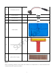
Lesson 16 LCD1602 Introduction I n this lesson, w e will learn how to use LCD1602 to display characters and strings. Components - 1 * Raspberry Pi - 1 * Breadboard - 1 * LCD1602 - 1 * Potentiometer - Jumper w ires Principle LCD1602 u o F d n r e Generally, LCD1602 has parallel ports, that is, it w ould control sev eral pins at the same time. LCD1602 can be categorized into eight-port and four-port connections.
Pin 7 (D0-D7): pins that read and w rite data A and K: controlling LCD backlight; K connects to GND, and A to 3.3V. Turn the backlight on and you can see the characters displayed clear in a dim env ironment LCD1602 has tw o operation modes: 4-bit and 8-bit. When the I Os of the MCU are insufficient, you can choose the 4-bit mode, under w hich only pins D4~D7 are used. After connecting the circuit, you can operate LCD1602 by the Raspberry Pi.
r e Note: After you run the code, characters may not appear on the LCD1602. You need d n to adjust the contrast of the screen (the gradual change from black to white) by spinning the potentiometer clockwise or anticlockwise, until the screen displays characters clearly. u o F For C language users: Step 2: Get into the folder of code cd /home/pi/SunFounder_Super_Kit_V3.0_for_Raspberry_Pi /C n u Step 3: Compile make 16_lcd1602 Step 4: Run sudo ./16_lcd1602 Code Explanation #include
lcdPosition(fd, 0, 0); // Locate the position of the cursor at Row 0 and Col 0 (in fact it's the first line and first column) lcdPuts(fd, "Welcom To--->"); // Display the character "Welcom To--->"on the LCD1602 lcdPosition(fd, 0, 1); lcdPuts(fd, " // Place the cursor at Col 0, Row 0. sunfounder.com"); while(1){ lcdClear(fd); for(i=0; i<16; i++){ // i adds one in the loop. i means the number of columns, so i adds to 16 at most.
self.used_gpio = self.pins_db[:] # Note down the used gpio to easily clear IO setting after the stop. pins_db[:] writes all in the pins_db list to the used_gpio list; if here use used_gpio = self.pins_db, it means used_gpio call pins_db, in other words, any change of pins_db will affect used_gpio. self.used_gpio.append(pin_e) self.used_gpio.append(pin_rs) self.write4bits(0x33) # initialization self.write4bits(0x32) # initialization self.write4bits(0x28) # 2 line 5x7 matrix self.
Further Exploration u o F d n r e I n this experiment, the LCD1602 is driv en in the 4-bit mode. You can try programming by yourself to driv e it in the 8-bit mode.
Lesson 17 ADXL345 Introduction I n this lesson, w e will learn how to use the acceleration sensor ADXL345. Components - 1 * Raspberry Pi - 1 * Breadboard - 1 * ADXL345 module - Jumper w ires Principle ADXL345 r e The ADXL345 is a small, thin, low pow er, 3-axis accelerometer w ith high resolution (13-bit) measurement at up to ±16 g. Digital output data is formatted as 16-bit tw o’s complement and is accessible through either an SPI (3- or 4-w ire) or I 2C digital interface.
r e Relationship betw een output and grav ity direction Pin Function of ADXL345 Module: u o F Name VS Supply Voltage Chip Select; I 2C mode is enabled if it's tie-high to VDD CS n u I /O (VDD I /O = 1.8V). SDO I NT1 I NT2 3.3V SDA SCL GND d n Description Serial Data Out, alternate I 2C address select S I nterrupt 1 Output I nterrupt 2 Output 3.
Experimental Procedures Step 1: Build the circuit u o F d n r e n u S The I 2C interface is used in the follow ing program. Before running the program, please make sure the I 2C driv er module of Raspberry Pi has loaded normally. For C language users: Step 2: Get into the folder of code cd /home/pi/SunFounder_Super_Kit_V3.0_for_Raspberry_Pi /C Step 3: Compile the Code make 17_adxl345 Step 4: Run sudo .
Code Explanation #include :> // Include functions and method for the IIC protocol #define DevAddr struct acc_dat{ 0x53 // device address // a struct variable to store the value of x,y,and z int x; int y; int z; }; fd = wiringPiI2CSetup(DevAddr); // This initialises the I2C system with your given device identifier void adxl345_init(int fd){ // Initialize the device by i2c wiringPiI2CWriteReg8(fd, 0x31, 0x0b); // These write an 8-bit data value into the device register indicated.
if(acc_xyz.y > 32767){ // Set the value of y as no more than 0x7FFF acc_xyz.y -= 65536; } if(acc_xyz.z > 32767){ acc_xyz.z -= 65536; } return acc_xyz; // The function ends, return to the acc_xyz struct } acc_xyz = adxl345_read_xyz(fd); // Call the function to read the data collected by the accelerometer module printf("x: %05d y: %05d z: %05d\n", acc_xyz.x, acc_xyz.y, acc_xyz.
if g > 32767: g -= 65535 res.append(g) return res accel = ADXL345() # Create an instance accel of class ADXL345 x, y, z = accel.read() # accel calls itself to measure x, y, and z and store them in a list. Then assign the values measured to x, y, and z. Now , rotate the acceleration sensor, and you should see the v alues printed on the screen change.