Preface About SunFounder SunFounder is a technology company focused on Raspberry Pi and Arduino open source community development. Committed to the promotion of open source culture, we strive to bring the fun of electronics making to people all around the world and enable everyone to be a maker. Our products include learning kits, development boards, robots, sensor modules and development tools. In addition to high quality products, SunFounder also offers video tutorials to help you make your own project.
Contents Introduction .............................................................................................................................................. 1 Components............................................................................................................................................. 2 A. Acrylic Plates .............................................................................................................................. 2 B. Mechanical Fasteners ...................
D. Steering Servo + Steering Linkage ....................................................................................... 39 E. Front Chassis + Upper Plate ................................................................................................... 40 F. Plates + Servo Rocker Arms ................................................................................................... 41 G. Pan/Tilt Servo + Plate .......................................................................................
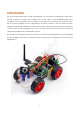
Introduction The SunFounder Smart Video Car Kit for Raspberry Pi is composed of Raspberry Pi, step-down DC-DC converter module, USB camera, DC motor driver, and PCA9685-based servo controller. From the perspective of software, the smart car is of client/server (C/S) structure. The TCP server program is run on Raspberry Pi for direct control of the car. And the video data are acquired and delivered via the open source software MJPG-streamer in a real-time manner.
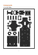
Components Su nF o un d er A.
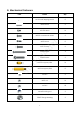
B. Mechanical Fasteners Name Qty. M1.2*4 self-tapping screw 8 M2*8 screw 6 M2.5*6 screw 16 M3*10 countersunk screw 2 M3*8 screw 8 er Parts 6 M3*30 screw 4 M4*25 screw 2 M2.5*8 copper pillar 16 M3*24 copper pillar 8 M2 nut 6 M2.
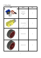
C. Drive Parts Parts Name Qty.
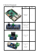
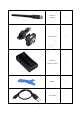
D. Electrical Components Parts Name Raspberry Pi 1 un d er Model B+ Qty.
USB Wi-Fi adapter 1 Su nF o un d er USB camera 1 6 18650*2 Battery holder 1 Ribbon 1 USB cable 1
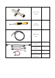
Cross socket wrench Cross 1 1 un d er screwdriver Cable Spiral Su nF o Wrap 20cm jumper wire (F to F) 10cm jumper wire (F to F) 10cm jumper wire (M to F) 20cm jumper wire (M to M) 7 1 4 5 2 2
E. Self-provided Parts The following parts are not included in the set. Parts Name Qty. Needed 18650 3.
Electrical Components Basics un d er A. Raspberry Pi Su nF o The Raspberry Pi is a low cost, credit-card sized computer that plugs into a computer monitor or TV, and uses a standard keyboard and mouse. It is a capable little device that enables people of all ages to explore computing, and to learn how to program in languages like Scratch and Python.
B. Step-down DC-DC Converter Module er Built based on the chip XL1509, the module converts the battery output of 7.4V to 5V, so as to supply power to Raspberry Pi and the servo. As a DC to DC converter IC, the chip has an un d input voltage ranging from 4.5V to 40V and generates an output voltage of 5V with a current of as high as 2A. Please note: only when the input voltage is up to 6.5V, a 5V output can be supported. Su nF o C.
rotates in a certain degree and does not rotate in a round circle. Also, the former is used for power supply by its whole-circle rotation, while the latter is applied to controlling the rotation angle of an object (like joints of a robot). Su nF o un d er D. DC Motor Driver As the name suggests, the module is used to drive DC motors. The driver is built based on L298N.
F. Servo Controller The Servo Controller is built based on PCA9685. PCA9685 is a 16-channel LED controller with I2C bus interface. The resolution ratio of each channel is 12 bits (212=4096 levels). The er controller works in a frequency between 40Hz and 1000Hz and its duty cycle can be adjusted in a range of 0 to 100%. It provides PWM signals for the servo and controls the rotation angle un d of the servo.
Assembly A. Back Half Chassis + Rear Wheels a) Assemble the following two acrylic b) When completed, the assembly should plates look like the figure below. Su nF o un d er c) Assemble the gear reducer, the active wheel and following acrylic plates with two M3*30 screws and M3 nuts. d) When completed, the assembly should look like the figure below.
e) Assemble the following two acrylic f) When completed, the assembly should plates look like the figure below. Su nF o un d er g) Assemble the gear reducer, the active wheel and the previously assembled part with two M3*30 screws and M3 nuts. h) When completed, the assembly should look like the figure below.
B. Back Half Chassis + Copper Standoffs b) When completed, the assembly should look like the figure below. un d er a) Assemble 4 M3*24 copper standoffs and 4 M3 nuts into the acrylic plate part as shown below. C. Upper Plate + Copper Standoffs Su nF o a) Assemble 16 M2.5*8 copper standoffs and 16 M2.5 nuts into the acrylic plate as shown below. Pay attention to the face of the plate. Refer to the small hole in the plate as pointed by the arrow in the following figure.
b) When completed, the assembly should look like the figure below.
D. Battery Holder a) Assemble the battery holder to the plate below with 2 M3*10 countersunk screws and 2 M3 nuts. un d er You can thread a ribbon through the plate below, so it will be easy to remove the battery, which is up to you. Su nF o b) When completed, the assembly should look like the figure below. c) The view from the top is as follows.
E. Back Chassis + Upper Plate un d er a) Connect the two assembled parts with 4 M3*8 screws. Su nF o b) When completed, the assembly should look like the figure below.
er c) The view from the back of the plate: un d F. Electrical Module Assembly Assemble the electrical components to the car with M2.5*6 screws. Su nF o See the figure below.
Circuit Connecting Preview: Looks complicated but don't worry! The detailed procedures will be given below, step by Su nF o un d er step.
Step 1: Connect the two DC motors with the motor driver. You may remove the L-shaped PCB connector and plug it back after wiring. Note: It doesn't matter how to wire the motors. After all the assembly is done, if the car moves in an opposite direction of what you control, just swap the wiring of the two motors and it will Su nF o un d er work normally.
Step 2: Connect the motor driver with the Raspberry Pi GPIO port based on the following table.
Step 3: Connect the servo controller with the Raspberry Pi GPIO port as follows: Servo Controller Pin 2 (5V) VCC Pin 3 (SDA) SDA Pin 5 (SCL) SCL GND GND Su nF o un d er Raspberry Pi GPIO Port 23
Step 4: Hook up the servo that controls the car's direction to CH0 of the servo controller, and the two servos that control the view of the camera to CH14 and CH15 respectively, as shown un d er below: Su nF o Step 5: Connect the motor driver with the servo controller.
Step 6: Connect the servo controller with the step-down DC-DC converter module. For the Su nF o un d er connector, loosen the screws, insert the wire, and then tighten the screws with a screwdriver.
Step 7: Connect the battery holder with the step-down DC-DC converter module and the DC motor driver. Note: Please DO NOT install the batteries at this step! Do it later when you've completed all the wiring. And take care that the red wire is the power and should be connected to the anode of the holder, when the black wire, i.e. the ground, to cathode. Su nF o un d er + - Insert the four wires into two jacks of the connector, two in each.
Su nF o un d er The whole picture of wiring should be like this: 27
Step 8: Connect the Raspberry Pi with the step-down DC-DC converter module, the USB Wi- Su nF o un d er Fi adapter and the USB camera.
Servo Calibration (Operation on Raspberry Pi) In the subsequent part of Operation on Raspberry Pi, you need to log into the Raspberry Pi REMOTELY instead of direct operation on a screen connected to the RPi – which is also impossible because the HDMI port on the smart car is blocked and cannot connect to one such display. So the back part of the car is completed. Next we'll move on to the front part. But before assembly, since servos are used in this part, they need some configuration for protection.
6) Create a blank file ssh under the /boot directory to enable remote login and delete the suffix in the file name. 7) Create a WiFi configuration file wpa_supplicant.conf under /boot and add the following to the file: ssid= "(name of the Wi-Fi)" Su nF o B. Car Power Supply un d er psk= "(your Wi-Fi password)" Now you can unplug the TF card from the PC and insert it into the Raspberry Pi.
er un d Su nF o Type in ssh pi@ip_address – ssh is the tool for remote login, pi, the user name, and ip_address, as the name suggests, your Pi's IP address. For example: ssh pi@192.168.0.101 Press Enter to confirm. If you get a prompt that no ssh is found, you need to install an ssh tool like Ubuntu and Debian by yourself: sudo apt-get install ssh For other Linux platforms, please contact your supplier.
For Windows Users If your computer runs on Windows, you need to pen the Bash shell with the help of some software. Here we recommend a tool PuTTY. 1. Download PuTTY 2. Open PuTTY and click Session on the left tree-alike structure (generally it's collapsed upon PuTTY startup).Enter the IP address of the RPi you just got in the textbox under Host Su nF o un d er Name (or IP address) and 22 under Port (by default it is 22) 3. Click Open.
This window is just like the Command Line window in Linux. D. Get Source Code Download the source code directly from Github to your Raspberry Pi. un d er cd ~ git clone https://github.com/sunfounder/Sunfounder_Smart_Video_Car_Kit_for_Raspb erryPi.git E. Install python-dev, python-smbus Install python-dev and python-smbus: apt-get apt-get apt-get apt-get update upgrade install python-dev install python-smbus Su nF o sudo sudo sudo sudo F.
cd ~/Sunfounder_Smart_Video_Car_Kit_for_RaspberryPi/server sudo python cali_server.py Then the contents of config are printed and the last line: Waiting for connection… er At this time, the servo might move a bit (this is the original position set). Su nF o un d Note: During the subsequent assembly, cali_server.py should keep running.
Continue to Assemble Note: Please keep cali_server.py running in the whole process of assembly. A. Front Wheels a) Fasten the F694ZZ flange bearing, driven wheel and following acrylic plates with an M4*25 screw and an M4 self-locking nut in the way as shown below. Use the cross socket wrench to fasten the M4 self-locking nut. Su nF o un d er Pay attention to the direction of this plate b) When completed, the assembly should look like the figure below.
d) Fasten the F694ZZ flange bearing, driven wheel and following acrylic plates with an M4*25 screw and an M4 self-locking nut in the way shown as below. f) Bear in mind that DO NOT over tighten the nut or else the wheel cannot turn flexibly. Neither too loose, in case the gap between the parts is too large. Su nF o un d e) When completed, the assembly should look like the figure below.
B. Steering Linkage + Servo Rocker Arm a) Connect the following acrylic plate to the second hole of the rocker arm (see the figure below) with an M2*8 self-tapping screw. The M2*8 self-tapping screw is contained in the package of the servo; it is one of the two longest screws. Su nF o un d er Also the rocker arm is packaged together with the servo. Note: Be careful with the screw of pricking your fingers.
C. Steering Servo + Upper Plate er a) Connect the servo to the acrylic plate below with two M2*8 screws and M2 nuts. Su nF o un d b) When completed, the assembly should look like the figure below. Note: The servo should be placed with its output shaft toward the front of the plate (see the following figure).
D. Steering Servo + Steering Linkage a) Connect the following parts with an M2*4 screw. The M2*4 screw is contained in the package of the servo; it is the shortest of the screws in the package. Keep the Steering Linkage perpendicular with the middle of the car; otherwise, remove it and mount again. DO NOT directly turn it in case of damaging the servo. Su nF o un d er Minor errors are allowed, which can corrected later by programming.
E. Front Chassis + Upper Plate Su nF o un d er a) Connect the following parts and wheels with M3*8 screws, M3*24 copper standoffs and M3 nuts, 4 for each. b) When completed, the assembly should look like the figure below.
F. Plates + Servo Rocker Arms b) When completed, the assembly should be like the figure below. un d er a) Connect the rocker arm of the servo to the acrylic plate below with 4 M1.2*4 screws. The rocker arm is packaged together with the servo. d) When completed, the assembly should be like the figure below. Su nF o c) Connect the rocker arm of the servo to the acrylic plate below with four M1.2*4 screws. The rocker arm is packaged together with the servo.
G. Pan/Tilt Servo + Plate un d er a) Connect the servo to the acrylic plate b) When completed, the assembly should below with two M2*8 screws and M2 nuts, look like the figure below. and we name it "pan servo". Su nF o c) Connect the servo to the acrylic plate d) When completed, the assembly should below with two M2*8 screws and M2 nuts look like the figure below. and we name it "tilt servo".
H. Pan Servo Plate + Tilt Servo Plate un d er a) Connect the two plate parts b) When completed, the assembly should together with two M3*10 screws and look like the figure below. M3 nuts. The two plates should be perpendicular to each other. Su nF o c) Connect the two parts at a right d) When completed, the assembly should angle with two M3*10 screws and M3 look like the figure below. nuts.
I. Servos + Rocker Arm Plates Top view: un d er a) Connect the following parts without any b) When completed, the assembly should screws. look like the figure below. The two plates as indicated with arrows below should be assembled in parallel; otherwise, remove and mount again. DO NOT directly rotate them in case of damages to the servo. c) Then fasten them with an M2*4 screw. Su nF o The M2*4 screw is contained in the package of the servo and is the shortest of the screws.
J. Mount + Car Su nF o un d er Assemble the mount part and the car with two M3*10 screws and M3 nuts. When completed, the assembly should look like the figure below.
------------------------ Now the car is completed. Congratulations! ----------------------------The car should be assembled successfully as shown below: Su nF o un d er To organize the wires, you can use the cable spiral wrap.
Car Calibration (Operation on PC) A. Get the source code Download the source code directly from Github to your PC at: https://github.com/sunfounder/Sunfounder_Smart_Video_Car_Kit_for_RaspberryPi, Or search for Sunfounder in Github and find the repository: Sunfounder_Smart_Video_Car_Kit_for_RaspberryPi. Su nF o un d er Click Download ZIP on the sidebar of the page, as shown below. After download, unzip the file. Find the file whose name containing "–master" and delete its suffix.
C. Run cali_client Run the calibration client on PC to connect the server on Raspberry Pi. For Windows users: Click the Start button on your computer, and type in python in the search bar, and you can find the IDLE (Python GUI). Click it and then a window will pop up. Click File -> Open -> Sunfounder_Smart_Video_Car_Kit_for_RaspberryPi-master -> client -> er cali_client.py to open this file, modify the value of HOST for the IP address of the Raspberry Su nF o un d Pi.
er Find the variable of HOST: Run cali_client.py: sudo python cali_client.py un d Enter your own address of the Raspberry Pi there. Press Ctrl+O to save and Ctrl+X exit. No matter what system your computer is running on, Linux or Windows, when you run Su nF o cali_client.py, a window Raspberry Pi Smart Video Car Calibration will pop up: In the terminal remotely connected with the Raspberry Pi, the IP address of the PC will be printed.
Then you can start calibrating. Before that, take out your package box and place it vertically with the side face to the table. Put the car onside the box and keep it balanced. The purpose is to keep the wheels of the car off the table. By default, the front wheels should be directly pointed towards the front; the camera on the un d D. Start Calibration er tilt servo should be face up no matter what directions the pan servo is pointed at.
If the reversing works normally, click Run again to stop the wheels from spinning. Turning Adjustment Currently the front wheels should be pointed at the exact front direction. But if it is not, you need to make some adjustments. In the Turning section in the Calibration window, click the left ( ) and right ( ) arrow buttons in the upper line to make fine adjustments, and those in the lower to coarsely adjust the turning direction. Keep adjusting until the wheels is oriented to the front exactly.
MJPG-streamer (Operation on Raspberry Pi) A. MJPG-streamer Installation Introduction The acquisition and transmission of video data by the SunFounder Smart Video Car is fulfilled based on MJPG-streamer. MJPG-streamer is a command line application that copies JPG-frame from a single input plugin to multiple output plugins.
sudo apt-get install libjpeg8-dev sudo apt-get install imagemagick Compile the source code of MJPG-streamer: cd /home/pi/Sunfounder_Smart_Video_Car_Kit_for_RaspberryPi/mjpg-streamer/mjpgstreamer sudo make USE_LIBV4L2=true clean all Install: sudo make DESTDIR=/usr install B. Testing Operation on Raspberry Pi sudo sh start.sh Su nF o un d Then the video data acquisition will start, like this: er Run the program: Type in the following address (replace 192.168.0.
54 er un d Su nF o
Get on the Road! A. Run TCP server (Operation on Raspberry Pi) Now a terminal's already open for remote login to the Raspberry Pi and run the mjpgstreamer, and you need to keep it RUNNING. Open one more to log into the Raspberry Pi to run tcp_server. Go to the directory with cd. cd ~/Sunfounder_Smart_Video_Car_Kit_for_RaspberryPi/server Then run tcp_server.py: sudo python tcp_server.
After modification, save the file and select Run -> Run Module. For Linux users: Open another terminal again. But DO NOT log into the Raspberry Pi remotely in this terminal. Go to the client with cd and edit the file client.py: Su nF o un d er Similar to changes in calibration, change the IP address in client program in your PC: After the alteration, press Ctrl + O and save and Ctrl + X to exit. Then run the client program: sudo python client_App.
You can click buttons such as Forward and Backward to control the car moving remotely. er Or click X+, X-, Y+, and Y- to control the coverage of the camera. Note: un d The server program must be run before you run the client program. Some settings must be completed for the server before the service is done. A communication endpoint needs to be created for the server to "listen" to requests from the client. Take the server as a receptionist or an operator of the bus phone in a company.
Program Analysis and Explanation Abstract From the perspective of software, the smart car is of C/S structure. The TCP server program is run on Raspberry Pi to listen to the command from the client and control the car accordingly. The client program is run on the PC and connected with the server through the TCP, which provides the user with a graphical user interface (GUI) to conveniently control the Raspberry Pi remotely. Both the client and server programs are written in Python.
1. Server Here we provide a pseudocode which creates a universal TCP server for explanation. Note that this is just one of the methods for server design. After you have a good knowledge about it, you can alter the pseudocode as you want: s = socket( ) # Create a socket for the server. s.bind( ) # Bind the address to the socket. s.listen( ) # Listen to the connection. inf_loop: # Indefinite loop of the server. c = s.accept( ) # Accept the connection from the client. comm_loop: # Communication loop. c.
un d er Process Diagram of Server Program Su nF o 2. Client It is easier to create a TCP client than to do a server. Take the following pseudocode: c = socket( ) # Create a client socket. c.connect( ) # Try to connect a server. comm_loop: # Communication loop. c.send( )/c.recv( ) # Dialog (sending out and receiving data) c.close( ) # Close the client socket. As mentioned above, all sockets are created via the function socket.socket( ). Then, the function connect( ) can be called to connect the server.
c) Create the GUI module needed on the object and enable the functions. d) Connect the GUI modules with the code at the system back-end. e) Enter the main event loop. Take a simple GUI program: Create a file Tk_test.py under the path /home: touch Tk_test.py Add executable privilege to the file: chmod +x Tk_test.py Open the file: vim Tk_test.py Type in the following code: er #!/usr/bin/env python from Tkinter import * un d top = Tk() # Create a top window top.title('Sunfounder.
Su nF o un d er Process Diagram of Client Program 62
Summary In this manual, having learned the related components for building the car kit, you've gone through the assembly of the mechanical parts and electrical modules with the knowledge of Raspberry Pi as well as a brief introduction of the key parts like servo, Wi-Fi adapter, etc. Also you've got a lot of software and coding, which lays a solid foundation for your future journey of exploring open-source field.
Copyright Notice All contents including but not limited to texts, images, and code in this manual are owned by the SunFounder Company. You should only use it for personal study, investigation, enjoyment, or other non-commercial or nonprofit purposes, under the related regulations and copyrights laws, without infringing the legal rights of the author and relevant right holders.