
User Manual

35
Procedures
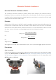
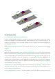
Step 1 Assembly
Connect the light follower to the Sensor Connector with M3*10 screws and M3 nuts, and then
assemble them to the car with two M3*10 screws and two M3 nuts. You're suggested to hold
the nuts underneath with your fingers.
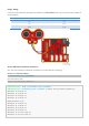
Step 2 Wiring
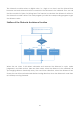
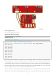
Connect the light follower to the Robot HATS with a 5-pin anti-reverse cable as shown below.
Light Follower
Robot HATS
AD2
A2
AD1
A1
AD0
A0
5V
3.3V
GND
GND
Note: You may wonder why we connect 5V to 3.3. Well, since the working voltage of the STM8
chip on the light follower is 2.7-5.5V, we can connect it to 3.3V here. DO NOT connect 5V to 5V! All
the analog ports on the Robot HATS are led from the PCA8591, which is powerd by 3.3V. Therefore,
if the voltage is between 3.3V-5V, the output value will always be 255, thus the PCA8591 may be
damaged if connected to 5V. Remember to connect to 3.3V.
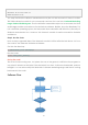
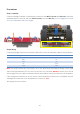
The wiring is shown as below: