Preface About SunFounder SunFounder is a technology company focused on Raspberry Pi and Arduino open source community development. Committed to the promotion of open source culture, we strive to bring the fun of electronics making to people all around the world and enable everyone to be a maker. Our products include learning kits, development boards, robots, sensor modules and development tools. In addition to high quality products, SunFounder also offers video tutorials to help your own project.
Contents Components List ........................................................................................................................................1 Constructure Plates ..............................................................................................................................1 Servo Accessories .................................................................................................................................1 Mechanical Fasteners ...............................
Software Flow ................................................................................................................................ 31 Code Explanation ........................................................................................................................ 33 Light Following .................................................................................................................................... 34 How It Works ............................................................
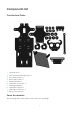
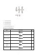
Components List Constructure Plates 1. Upper Plate x 1 2. Hex Front Wheel Fixing Plate x 6 3. Front Half Chassis x 1 4. Back Half Chassis x 1 5. Bearing Shield x 6 6. Ultrasonic Connector x 1 7. Steering Linkage x 1 8. Ultrasonic Support x 1 9. Steering Connector x 2 10.
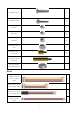
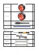
1. 1-arm Rocker Arm 2. 2-arm Rocker Arm 3. 4-arm Rocker Arm 4. Rocker Arm Screw 5. Rocker Arm Fixing Screw × 2 Mechanical Fasteners Name Component Qty. M2x8 Screw 2 M2.5x6 Screw 4 M2.
M3x25 Screw 4 M4x25 Screw 2 M2 Nut 2 M2.5 Nut 12 M3 Nut 23 M4 Self-locking Nut 2 M2.5x8 Copper Standoff 8 M3x25 Copper Standoff 8 4x11x4 F694ZZ Flange Bearing 2 Wires 100mm HX2.54 5-Pin Jumper Wire 1 50mm HX-2.54 4Pin Jumper Wire 1 50mm HX-2.54 2Pin Jumper Wire 1 100mm HX-2.
200mm HX2.54 5-Pin Jumper Wire 200mm HX-2.54 4-Pin Jumper Wire 200mm HX2.
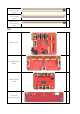
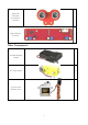
Ultrasonic Obstacle Avoidance Module 1 Light Follower Module 1 Other Components 2x18650 Battery Holder 1 DC Gear Motor 2 SunFounder SF006C Servo 1 5
Rear Wheel 2 Front Wheel 2 USB Wi-Fi Adapter 1 Ribbon (30cm) 1 Tools Cross Screwdriver 1 Cross Socket Wrench 1 M2.
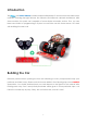
Introduction The is a SMART SENSOR car robot based on Raspberry Pi, which comes with three sensor modules, including the light follower, line follower and ultrasonic obstacle avoidance. With these modules, this smart car is capable of some simple automatic actions. Thus, you can learn some basics of programming in Python to control the car with these sensors.
Fixing Rear Wheels Assemble the two motors with four M3x25 screws and M3 nuts. Pay attention to place the motors with wires inward, providing convenience for connecting the circuit. Place wires inwards So now this part is completed. You can put it aside for now.
Upper Plate Mount the M2.5x8 copper standoffs and M2.5 nuts into the upper plate first. Four copper standoffs are needed. So here 4 holes should be used, marked with cross as shown below: Assemble the M2.5x8 copper standoffs and M2.5 nuts as shown below. Pay attention that the side the protruding prop should face up.
Battery Holder Turn the Upper Plate upside down. Cut the ribbon into two halves. Thread them through the holes on the plate. Pay attention to the direction and leave one end longer out of the plate for each to remove the battery easily later. Fasten the battery holder with two M3x8 countersunk screws and two M3 nuts: pay attention to the direction of battery holder’s wire.
Rear Wheels (Screws) Insert four M3x8 screws with four M3x25 copper standoffs: 11
PCB Assembly Assemble the Raspberry Pi (TF Card inserted) with eight M2.5x8 copper standoffs, then plug the Robot HATS onto it, and fix the Robot HATS with four M2.5x6 screws. Fix The PCA9685 PWM Driver, the TB6612 Motor Driver with eight M2.5x12 screws and M2.
Rear Wheels (Driving) Assemble the rear wheels 13
Align the rear wheels with the motor shaft, and rotate to insert them gently.
Front Wheels Note: Please pay attention to the direction of Steering Connector before assembling. Insert an M4x25 screw through a Flange Bearing (pay attention to the direction – the flange near the cap of the screw), a Steering Connector, 3 Bearing Shields, 3 Hex Front Wheel Fixing Plates, and a front wheel, into an M4 Self-locking Nut (note the direction) as shown below: Flange The Self-locking Nut should be screwed tight enough.
Steering Part Take out the Rocker Arm and the Rocker Arm Screw (the longer one): Connect the Steering Linkage and the rocker arm with the screw. Note: Insert it into the first hole of the arm (as indicated by the arrow below) which is the farthest from the gears. Since the screw is larger than the hole, you should try to screw it hardly so as tight to the arm. Don't worry of the arm which is soft.
And also fasten them as tightly as possible, and then loosen the screw a little so the Steering Linkage can move flexibly. Mount the steering servo to the Upper Plate with two M2x8 Screws and two M2 nuts (pay attention to the direction of the servo wires): Till here the car assembly is mostly done. But don’t hurry to assemble the front wheels, because the servo has not been adjusted yet. An unadjusted servo may get stuck and further get hot and burnt when it is connected to power to use as it is.
Circuits Building Connect the PWM CONTROL of the Robot HATS with the PCA9685 PWM Driver, and the TB6612 CONTROL with the TB6612 Motor Driver. Then the Left Motor and the Right Motor of the TB6612 to two motors, and the Motor PWM with the No. 4 and 5 PWM channel of the PCA9685. Connect the PWM Power of the PCA9685 with the Robot HATS, and its channel 0 of with the Turning Servo.
So now the circuit boards are all installed onto the car and the wiring is done. But still you're not ready to adjust the servo yet. First you need to complete some software installation.
Software Installation 1. Log into Raspberry Pi The TF card onto which the Raspbian has been burnt is inserted into the Raspberry Pi before. Now power the Raspberry Pi. The installation may take a long time, so you're recommended to so you're recommended to supply the Raspberry Pi via a USB cable and then power the Robot HAT with batteries in case of power cut-off thus causing a sudden shutdown and file damage of the Raspberry Pi.
Cloning into 'example/SunFounder_Line_Follower'... remote: Counting objects: 8, done. remote: Total 8 (delta 0), reused 0 (delta 0), pack-reused 8 Unpacking objects: 100% (8/8), done. Checking connectivity... done. Submodule path 'example/SunFounder_Line_Follower': checked out '9560e7adbb52a883d438b 78de90d185fc168fed5' Cloning into 'example/SunFounder_Ultrasonic_Avoidance'... remote: Counting objects: 24, done.
1. Update the apt list sudo apt-get update 2. Install python-smbus sudo apt-get install python-smbus -y 3. Install the PiCar module cd ~ git clone --recursive https://github.com/sunfounder/SunFounder_PiCar.git cd SunFounder_PiCar python setup.py install 4. Enable I2C Edit the file /boot/config.txt sudo nano /boot/config.txt The "#" in front of each line is to comment the following contents which does not take effect in a sketch. The I2C configuration part is commented by default too.
immediately, but all servos will keep at 90 degrees. You can continue the rest assembly. Warning: After power is on, a short circuit may happen because the exposed contacts of the PCB may be touched by conductive objects like screw or screwdriver. If it occurs, please remove the conductor immediately or unplug the power as quickly as you can.s Build the Rest of the Car Connect the Steering Linkage and the rocker arm. Make sure the rocker arm is in an angle as shown below.
Then put the assembled Front Half Chassis onto the Upper Plate with standoffs aligned with the holes. Hold them carefully, turn upside down, and fasten the standoffs and the Uppe Plate with four M3x8 screws: Now, the whole assembly, the wiring and code are all DONE! Congrats! Enjoy the satisfaction and thrill.
Configuration Remember the commands to adjust the servo to 90 degrees previously? Now, let’s talk about the other two commands. The second command front-wheel-test is used to test whether the front wheels can turn flexibly after assembly. When you run this command, it will drive them to turn left and right. Besides, there is an optional parameter [chn]. It will be used only when you change the PWM channel of the servo.
number; to make it more towards the left, you can set it smaller (it can even be a negative number). But DO NOT over-configure the wheels (recommended a value between -30 and 30), or the servo may be stuck and broken. pi@raspberrypi:~/SunFounder_PiCar/picar $ nano config GNU nano 2.2.
Forward, Forward, Forward, Forward, Forward, Forward, Forward, Forward, speed = 3 speed = 4 speed = 5 speed = 6 speed = 7 speed = 8 speed = 9 speed = 10 . . . Backward, speed = 10 Backward, speed = 9 Backward, speed = 8 Backward, speed = 7 Backward, speed = 6 Backward, speed = 5 Backward, speed = 4 Backward, speed = 3 Backward, speed = 2 Backward, speed = 1 Finished, motor stop Check whether both the two rear wheels rotate direction is the same as the screen promt.
Arming the Car! A car without sensor modules is unarmed just like a man without sight and hearing, thus he has no feeling for the surrounding environment. So what we are going to do is arm the car, allowing it to detect the surroundings. Now let’s turn the PiCar into the PiCar-S. What exactly is the PiCar-S? ------- We arm the PiCar with some sensors, which endow the car with the ability to collect and process the data.
Ultrasonic Obstacle Avoidance How the Obstacle Avoidance Works The ultrasonic obstacle avoidance module detects and transfers the collected data to Raspberry Pi that can calculate the distance from the obstacle. The Pi will send a command to adjust the front wheels and rear wheels direction and rotation to control the PiCar-S walk away from the obstacle if there is one.
Step 2. Wiring Connect the ultrasonic obstacle avoidance to Robot HATS with a 3-pin anti-reverse cable as shown below. Ultrasonic Obstacle Avoidance Robot HATS SIG D0 5V 3.3V GND GND Test for Ultrasonic Obstacle Avoidance First, test the ultrasonic obstacle avoidance module before applying. Get into the directory example: cd ~/SunFounder_PiCar-S/example/ Run the test code: python test_ultrasonic_module.
distance 13 cm less than 17 distance 10 cm less than 17 Read distance error You may find that the distance measurement may be not that accurate. It doesn’t matter. This 25kHz ultrasonic module is not a commonly used one, but one has a horizontal detecting range of about 30~40 degrees. Thus the distance measured may be not so accurate, but that small range provides convenience for obstacle avoidance.
The ultrasonic module returns a digital value, i.e., High or Low level, and the interval time between two levels returned can be converted to the distance to the obstacle. Thus, we call the time module in Python for timing here. The formula to calculate the distance is written in the ultrasonic module’s driver. The main program just calls the corresponding program to get the distance value.
Turn Backward Forward Code Explanation ua = Ultra_Sonic.UltraSonic_Avoidance(17) Create an object ua of a UltraSonic_Avoidance class in the Ultra_Sonic module. The number in the round bracket is the initial parameter, which represents the pin number the SIG of the module is connected to. Since the BCM naming method is applied, the corresponding pin on the Raspberry Pi is #17. back_distance and turn_distance, two constants are to set the thresholds of the ranging distance.
larger the number (within the range 0-100) is, the faster the wheel rotates. fw.turn(angle), function in the back_wheels, to set the turning angle. The angle is 90 when the car moves straight forwards; reduce the number to turn left, and increase it to turn right. fw.turn_straight(), making the front wheels return to the angle of moving straight forwards.
Procedures Step 1 Assembly Connect the light follower to the Sensor Connector with M3*10 screws and M3 nuts, and then assemble them to the car with two M3*10 screws and two M3 nuts. You're suggested to hold the nuts underneath with your fingers. Step 2 Wiring Connect the light follower to the Robot HATS with a 5-pin anti-reverse cable as shown below. Light Follower Robot HATS AD2 AD1 AD0 5V GND A2 A1 A0 3.3V GND Note: You may wonder why we connect 5V to 3.3.
Test for Light Follower Let’s test the light follower first. Get into the directory example cd ~/SunFounder_PiCar-S/example/ Run the test code python test_light_module.py pi@raspberrypi:~ $ cd ~/SunFounder_PiCar-S/example/ pi@raspberrypi:~/SunFounder_PiCar-S/example $ python test_light_module.
the light follower module under the natural light (or other bright conditions) to get the output value; then shine the flashlight on the phototransistors to get another output value. A place with a gap of 20+ between these two values would be a better choice, so that we can get an obvious effect when the car follows light. Step 3 Run the Code Get into the directory cd ~/SunFounder_PiCar-S/example Run the code python light_follower.
2. Here write two main functions/modules including light following calibration and light following in the main program.
Run light following subfunction Read the probe's status [1,0,0]or[1,1,0] [0,0,1]or[0,1,1] [0,1,0]or[1,1,1] [1,0,1] move backwards [0,0,0] turn left move straight forwards turn right stop temporarily and return to standby mode The light follower includes three phototransistors, thus its status list is composed of three elements which represent 8 statuses (based on permutation and combination). And here we need to set related responses to these statuses.
angle and small-angle turning. If the light is at the central left side (status [1,1,0]), we should apply a small-angle turning; if the light is at the edge of the left side (status [1,0,0]), we should apply a large-angle turning. Code Explanation To understand the code, take the software subflows above for reference. Three Python modules are used in the code including the imported light_follower_module, front_wheels, and back_wheel previously.
bw.set_speed(forward_speed) Here we need two functions for rear wheels. The first function is to control the rotating direction as forward (the function for backwards is bw.backward()). The second one is to set the rotating speed of the wheels; the parameter is the speed value (range: 0-100). The bigger the parameter is, the faster the wheel rotates. Line Following How to Follow Lines The line follower detects lines in the surrounding environment, and transfers the data to the processor.
Step 2 Wiring Connect the line follower module to the Robot HATS with a 4-pin anti-reverse cable as shown below. Line Follower Robot HATS SCL SDA VCC GND SCL SDA 3.
We can see 11 is the line follower’s i2c address. If it is not shown, it proves your wiring is not correct and the i2c communication with Raspberry Pi fails too. You need to check the wiring before the next step. Run the test code python test_line_module.py pi@raspberrypi:~/SunFounder_PiCar-S/example/ $ python test_line_module.
itself. How to make a track for line following To make a track for the car to follow a black line, you need to prepare the following materials: A large sheet of paper, a roll of black tape (as black lines), a hard card board (the size depending on the size of the track) or a flat surface like the floor or desk. 1. Spread the paper out smoothly on the hard board, and paste on the board or flat surface. 2. Paste the tape on the paper. Rules for making: 1.
Software Flow Considering the interference of negative environment factors, we need to calibrate the line follower sensor before actual use. Here two main functions including the line follower calibration and line following are included in the main program.
Line follower calibration function Prompt user to calibrate for white color Prompt user to calibrate for black color Delay for user to place the sensor above white surface Delay for user to place the sensor above black line Sensor reads the average value Sensor reads the average value Prompt user: white color calibration done Prompt user that black color calibration done White color calibration Black color calibration Subflow of Line Following Function 46 Take the average value for each sensor
In the line following function, we set the turning angle of the servo in different levels according 47
to the detection results of the probes. If the line in front of the car is detected as a small curve, then the car will turn a small angle; if it is a big one, the car will turn a large angle. Thus, here we set four angle-turning constants: a_step, b_step, c_step, and d_step. When the car moves forward originally, the servo is in 90 degrees. To drive the car to turn left, the servo should be in 90+step degrees; to turn right, the servo should be in 90-step degrees.
response program to let the car move backwards in the opposite direction (3), and then turn back to the original direction until a black line is detected again and move forward (4). Code Explanation The logic of the code is just as shown in the flow chart above. Three Python modules are used in the code, including the imported SunFounder_Line_Follower, front_wheels, and back_wheels.
Combination So, this smart car now is smart in three separate features. But, you think only one sensor module is not enough? Try to combine those sensor modules in one! Here we can show you an experiment - light following with obstacle avoidance for referece.
Start Run light follower calibration function Calibration Detect obstacles N avoid_flag == 2 If an obstacle detected, move backwards avoid_flag == 1 Else If close to an obstacle, turn away If no obstacle found, keep following light Run light following program Light following subfunction Interrupt Y End Since the light following and obstacle avoidance of the car depend on the sensor modules, we set two functions to read the status of two sensors separately, and assign values to flags to be ret
if the spot is at the left side, it will return light_flag = 2; if the spot is at the back, it will return light_flag = 3; if no light spot is detected, it will return light_flag = 4. The main program main() will run the corresponding program according to avoid_flag and light_flag, and the avoid_flag is superior in priority.
Appendix Appendix 1: Modules Robot HATS Robot HATS is a specially-designed HAT for a 40-pin Raspberry Pi and can work with Raspberry Pi model B+, 2 model B, and 3 model B. It supplies power to the Raspberry Pi from the GPIO ports. Thanks to the design of the ideal diode based on the rules of HATS, it can supply the Raspberry Pi via both the USB cable and the DC port thus protecting it from damaging the TF card caused by batteries running out of power.
5 . UART port: 4-wire UART port, 5V VCC, perfectly working with SunFounder FTDI Serial to USB. ○ 6 . TB6612 motor control ports: includes 3.3V for the TB6612 chip, 5V for motors, and direction ○ control of motors MA and MB; working with SunFounder TB6612 Motor driver. 7 . Switch: power switch ○ 8 . Power indicators: indicating the voltage – 2 indicators on: >7.9V; 1 indicator on: 7.9V~7.4V; ○ no indicator on: <7.4V.
TB6612 The TB6612 Motor Driver module is a low heat generation one and small packaged motor drive.
The TCRT5000 infrared photoelectric switch adopts a high transmit power infrared photodiode and a highly sensitive phototransistor. It works by applying the principle of objects' reflecting IR light – the light is emitted, then reflected, and sensed by the synchronous circuit. Then it determines whether there exists an object or not by the light intensity. It can easily identify black and white lines.
convert the voltage into digital values by the A/D converter on the MCU. And we can tell the light intensity then by this value. The module can be used to sense the ambient luminance. The blue potentiometer is to adjust the sensitivity – you can change it to adapt to specific circumstances. There are two mounting holes of 3mm diameter on the module for easy assembly on your robot. Ultrasonic Obstacle Avoidance Module This module contains an ultrasonic sensor to detect the distance to an obstacle in front.
The SunFounder SF0180 Servo is a 180-degree three-wire digital servo. It utilizes PWM signal of 60Hz and has no physical limit – only control by internal software to 180 degrees at most. Electrical Specifications: Item V = 4.8V V = 6.0V Consumption Current* (No Load) ≦50mA ≦60mA Stall Current ≦550mA ≦650mA Rated Torque ≥0.6 kgf·cm ≥0.7 kgf·cm Max. Torque ≥1.4 kgf.cm ≥1.6 kgf.cm No Load Speed ≦0.14sec/60° ≦0.12sec/60° WiFi Adapter The Ralink RT5370 Wireless Adapter is used in the car.
Copyright Notice All contents including but not limited to texts, images, and code in this manual are owned by the SunFounder Company. You should only use it for personal study, investigation, enjoyment, or other non-commercial or nonprofit purposes, under the related regulations and copyrights laws, without infringing the legal rights of the author and relevant right holders.