Preface About SunFounder SunFounder is a technology company focused on Raspberry Pi and Arduino open source community development. Committed to the promotion of open source culture, we strive to bring the fun of electronics making to people all around the world and enable everyone to be a maker. Our products include learning kits, development boards, robots, sensor modules and development tools. In addition to high quality products, SunFounder also offers video tutorials to help you build your own project.
Contents Introduction .......................................................................................................................... 1 1.1 Overview ........................................................................................................... 1 Components List ................................................................................................................. 2 2.1. Acrylic Plates ..........................................................................................
Introduction 1.1 Overview RollFlash is a good learning kit for Arduino and robot hobbyists. Since it moves slowly just like Flash in Zootopia, it is named RollFlash - moves really like a "flash". With an open source Arduino Nano board for control, a Servo Control Board, and a Bluetooth Module, it walks slowly with eight SF servos (9g) driving four legs. Equipped with an ultrasonic module on the front, it can avoid obstacle easily; with an infrared module at the bottom of the front, it follows lines.
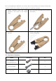
Components List Su nF o un d er 2.1. Acrylic Plates 1. Bottom Plate x 1 2. Ultrasonic Fixing Plate x 1 3. Support Plate x 2 4. Joint Connector x 8 5. U3 Plate x 4 6. Upper Plate x 1 7. U2 Plate x 4 8. Crus x 4 9. U1 Plate x 8 10.
Prior to assembling the RollFlash, you need to remove the residues in the holes of the plates and the stickers on the plates. Here we take the U1 plate for example. 2. Use a tool with a pointed end to remove the residue. 3. Make sure that all the residues are cleared. 4. Use the pointed tool to scratch off the sticker on the plate. Su nF o un d er 1. Check whether there are some residues in the holes of the acrylic plate. 2.2. Mechanical Fasteners Name Accessory M1.2*4 Qty.
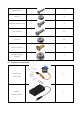
16 M2 Nut 16 M3*8 Flat-Head Screw 2 M3*10 Screw 36 M3 Nut 38 φ3*φ8*4 Flange Su nF o Bearing un d M3*6 Corn Rivet er M2*8 Screw 4 8 2.3.
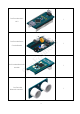
SunFounder Nano 1 V4.
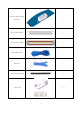
SunFounder Infrared 1 Module 1 6-Pin Jumper Wire 1 un d Su nF o Mini USB Cable er 4-Pin Jumper Wire Riband 1 1 Heat Shrink Tubing 6 Wire Clip 2 6
4 Transparent Tape 1 er Sponge Bag 1 2.4. Tools Su nF o un d Shell Philips Screw Driver 1 2.5.
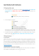
Get Started with Software 3.1 Download the code 1. Prior to the project, you need to go to our website www.sunfounder.com on LEARN->Get tutorials->Robot Kit->Rollflash Bionic Robot Turtle for Arduino and download the package: In the package you can see: Su nF o un d er 2. Included are the code for the kit, schematic diagrams of the modules, the app installer for Android phones, driver for Nano board, and the 3D printer file Rollflash.stl for the shell. 3.
In this kit, SunFounder Nano board is used. 3.2.3 Install Arduino IDE The code in this kit is written based on Arduino, so you need to install the IDE first. Skip it if you have done this. er Step1: Go to the arduino.cc website and click Download. On the page, check the software Su nF o un d list on the right side under Download the Arduino Software. Find the one that suits your operation system and click to download. There are two versions of Arduino for Windows: Installer or ZIP file.
Su nF o un d er Choose Next. Click Browse to choose the installation path or enter a directory at the Destination Folder. Click Install.
The following interface will show up. Note: After the installing progress bar goes to the end, er the Close button may be enabled for some PC. Just click it to complete the installation. Su nF o un d Then a prompt appears. Select Always trust software for "Adafruit Industries" and click Install. Select Always trust software for "Arduino srl" and click Install.
After the installation is done, click Close. Then an Arduino icon will appear on the desktop: 3.2.4 Install the Driver If the driver is not installed, the Nano board will not be able to be recognized by your computer. Therefore, before using it, please install appropriate driver. For Windows users, run PL2303_Prolific_DriverInstaller_v1.10.0.exe in the folder Rollflash Bionic Robot Turtle for Arduino.
Assembly 4.1 Upper Plate + Riband Su nF o un d er 1. Cut the 30cm ribbon into halves. Thread the ribbon through the acrylic plate. Leave the riband with one end longer on one side of the plate (onto which to fix the battery holder). Thread the other half through the upper plate in the similar way. 4.2 Upper Plate + Battery Holder 1. Place the battery holder on the upper plate. Note: Leave the holder’s wires in the tail direction. 2. Fasten the battery holder with two M3*8 screws and two M3 nuts.
4. Install the batteries. Pay attention to the anode and cathode in case of inserting inversely. er 3. Fold the ribbons in the battery box. Su nF o un d 5. It should be like this after the installation: 4.3 Upper Plate + Servo 1. Align a servo with a servo slot on the 2. upper plate. Pay attention to the direction of servo wires (shaft toward the head). 14 Assemble the servo into the plate.
3. Align two M2 nuts with the servo 4. mounting holes, and fasten them with two M2*8 screws. It should look like this: Su nF o un d er 5. Mount the other three servos in the same way. Pay attention to the direction of servos’ shaft (as shown below). 4.4 Upper Plate + PCB 1. Align the four acrylic washers with the holes of the upper plate. 2. Place the washers on the plate.
4. Insert four M3*10 screws through holes on the Servo Control Board, 4 acrylic washers, and into 4 M3 nuts, and tighten them. The assembly should be like this: un d er 3. Put Servo Control Board onto the upper plate. Make sure the power port of the board is at the rear part, and that the four mounting holes are well aligned with those on the plate. 6. Insert the pin into headers. Su nF o 5. Plug the SunFounder Nano onto the Servo Control Board.
7. Align the pins on the Bluetooth Module with the female headers on the Servo Control Board as shown below. 8. Insert the Bluetooth Module into the board. er 4.5 U Joint-A/U joint-B Su nF o un d 1. Align the rocker arm with the mounting 2. Assemble the arm to the plate with two holes on U1 plate. M1.2*4 self-tapping screws in the first and last small holes of the rocker. 3. Align the bulges of the assembled U1 plate with concaves of the Joint Connector. 4. 17 Insert the bulges into the concaves.
5. Place an M3 nut in the groove of the 6. rocker fixing plate, and insert an M3*10 screw from below into the nut. er 8. Place an M3 nut in the groove of U2, plate and insert an M3*10 screw from below into the nut. Su nF o un d 7. Insert the U2 plate into the connector plate. Note: The size of the end hole near its arc is different from U1. Tighten the screw. 9. Tighten the screw. Now such a U joint (type-A) is assembled.(U1+U2) 10. Assemble the other kind of U joint (typeB) in the same way.
11. So four type-A U joints are assembled as shown below: Small hole on the side without rocker un d er arm - Tyep A 12.
4.6 U Joint Unit-1/U Joint Unit-2 2. Place them close. un d er 1. Assemble a type-A U joint with a type-B U joint perpendicularly as shown below. Align all the 4 mounting holes in the middle of the two connector plates. Su nF o 3. Insert two M3*10 screws from the type-A 4. Tighten the screws. Now a U joint unit U joint's side through the middle two (type-1) is done. holes in row, and fix them with two M3 nuts on the other side.
5. Connect another unit of type-A + type-B U joint in the same way. Now we have two type-1 units. Large hole on er the right Su nF o un d 6. Connect the rest U joint units in the similar way, but remember to rotate the type-B U joints 180 degrees when connecting. Now, we have two type-2 units as shown below.
4.7 Crus + Servo 2. Assemble the crus to the servo. un d er 1. Align the hole of the crus plate with the servo. Pay attention to the direction of the crus and the crus (foot) as shown below. 4. Su nF o 3. Connect the two components with two M2 nuts and M2*8 screws. 22 Tighten the screw.
Now, we have two assembled crura of this type. 6. Assemble the other two symmetric crura in the same way. Pay attention to the direction of the feet when inserting the servo into the hole. Su nF o un d er 5.
4.8 Uploading Assembly Program Note: Before installing the rocker arm for each servo, you need to adjust the servo. Connect the servo wires to the port D2 of the Servo Control Board and configure the initial position of the servo. Step 1: Hook the servo wires to D2, connect the Servo Control Board to PC via a USB cable, un d er and the PC will automatically install the driver. The COM port connected will appear. Step 2: Go to the folder Rollflash Bionic Robot Turtle for Arduino\Code\Basic\1.
And Port. Su nF o un d er Step 4: Click Upload. After the upload is completed successfully, unplug the USB cable and press the switch on the board. You may hear the sound of gear moving (or may not, if the servo shaft happens to be at 90 degrees at the beginning; but you GENTLY spin the rocker arm and you'll find it's unmovable). So now the servo is adjusted to 90 degrees.
4.9 U Joint Unit + Crus Align the φ3*φ8*4 flange bearing with 2. the hole in the type-2 U joint unit. Insert the flange bearing into the hole. er 1. Su nF o un d 3. Make sure the crus is perpendicular to 4. Insert an M2*4 self-tapping screw into the the U1 plate as shown below. If not, servo shaft and tighten them. gently pull out the servo and insert it again in case of damage caused by spinning the shaft. Slightly open the U1 joint to insert the servo shaft on the crus into the hole on the joint.
Assemble the crus to the other Type-2 U joint unit. Su nF o 7. un d er 5. It should be like this. After one leg is 6. Assemble the other similar leg. DO adjust done, unplug the servo wires connected all servos by connecting to D2 before to D2 for connection of the next servo. assembling each leg.
Assemble two crura to the type-1 U joint units in the same way. Su nF o un d er 8. 4.10 Upper Plate + Leg 1. Align the M3*6 Corn Rivet with the hole 2. on U2 plate from the inside of the Type-A U joint.
5. Tighten the screw. Align an M2*4 self-tapping screw with the hole of the servo rocker arm on the upper plate. un d Su nF o 45° Note: Remember to unplug the servo wires connected to D2 for connection of the next servo. er 3. Connect the servo to Port D2 on the 4. Servo Control Board for calibration. Keep the leg and the servo in 45 degrees. Open the U1 plate a little to insert in the servo connected to the upper plate. Also DO NOT open too much in case of plate breaking. 6.
4.11 Bottom Plate + Sensor 4. Tighten the screws. There will have a small gap between them because of the pins on the ultrasonic module. Su nF o un d 3. Align four M1.6*10 screws and four M1.6 nuts with the mounting holes as shown below. Mount the module on the plate. er 1. Align the ultrasonic module with the 2. mounting holes on the ultrasonic fixing plate. 5. Align the module with the slot on the bottom plate as shown below. Make sure the module’s port is upwards. 6.
7. Place an M3 nut in the groove of the 8. module, and insert an M3*10 screw from underneath as shown below. Tighten the screw. Su nF o un d er 9. Insert two M3*10 screws into the infrared 10. Insert the screws through two acrylic module from underneath. washers. 11. Insert these two M3*10 screws through 12. Tighten the screws. the bottom plate and two M3 nuts as shown below.
13. Align the bulges of the support plate with the holes on the bottom. 14. Insert the support plate. Su nF o un d er 15. Place an M3 nut in the slot of the support 16. Tighten the screw. plate. Align an M3*10 screw from below. 17. Fix the other support plate on the bottom plate in the same way. 18. Align four φ3*φ8*4 flange bearings with the holes on the bottom plate.
19. Insert them into the bottom plate. 20. Insert the 6-pin anti-reverse cable into the port of the infrared module as shown below. er 4.12 Upper Plate + Bottom Plate Su nF o un d 1. Thread the 6-pin anti-reverse cable through the wire slot on the upper plate. Align the bulges of the support plate and the ultrasonic plate with the mounting holes on the upper plate.
un d er 2. Connect the support plate to the upper plate. Before that, you need to insert the four rivets on the U joints into the flange bearings on the bottom plate. Su nF o 3. Insert three M3*10 screws from the upper bottom plate through the bottom plate into M3 nuts.
4. Fasten then screws. 4.13 Wiring 1. The servos and pin headers on the Servo Control Board are marked number 1-8 as shown Su nF o un d er below. Connect the servos to the corresponding ports. Pay attention that the yellow wire should be toward the tail direction. Then insert the 6-pin cable into the 6-pin port. Connect the ultrasonic module to the Servo Control Board with a 4-pin cable. (Here we provide six heat shrink tubing to wrap the servo wires, 4-pin cable and 6-pin cable.
4.14 Shell The shell provided in the kit is a paper-made one for decoration. You can assemble it if you want. Here we will show you how to assemble the shell. 2. Fold the shell along the white lines, and use the transparent tape to stick two adjacent plates together on the inside. 3. Remove the sticker on the bulging edge of the shell as shown below. 4. Fit the shell with the upper plate. Press the shell gently to stick to the plate. er The unfolded shell is shown as below. Su nF o un d 1. 5.
Experiments As we all know, tortoise is a reptile with four feet, so does this quadruped RollFlash. On each leg there are two servos, thus it can complete actions including moving forward and backward, turning left and right, etc. with these eight servos. What’s more, equipped with a Bluetooth module, ultrasonic module, and infrared module, it can be controlled on an Android phone by app, avoid obstacles, and follow lines. Let’s go further into the basic programs and game programs. 5.
4) Back to RollmanAPP, tap Select Device -> ELET_SPP_ XXXXXX, and then hit Connect. 5) If the Bluetooth has been connected to the Bluetooth of the mobile successfully. The icon Connect in the App will become connected. The Status LED in the Bluetooth will keep Su nF o un d er constantly lighting instead of blinking. Now you can control the RollFlash to go forward, backward, turn left and right just on your phone.
5.2 Obstacle Avoidance An ultrasonic module is installed on the robot, so it can detect obstacles ahead and measure the distance, at last avoiding the obstacles in front. 1. Open the code file Avoidance.ino under the path Rollflash Bionic Robot Turtle for Arduino/Code/ 3. Avoidance and upload to the RollFlash. 2. Construct a building for the robot to play. You can see it can avoid obstacles independently. Or just put some barriers for it and observe whether it can bypass.
3. You can place some obstacles on the line to see the RollFlash bypass them when Su nF o un d er following the line. It's quite fun to draw the lines and figures aside. Just keep the tips in mind when playing. 5.4 Dance The code file Dance.ino under Rollflash\Rollflash Bionic Robot Turtle for Arduino\Code\5. Dance\Dance, as the name suggests, is to make the RollFlash dance. Upload the code to the board and the robot will just dance.
Code Explanation 6.1 ServoWrite.ino Looking at the code folders, you may find that on matter for the app, the obstacle avoidance function or the line following, there is always a sketch ServoWrite.ino. Actually it's for servo control, so no wonder. You can check the description below for the code. Su nF o un d er Control the servo on pin 2 The program above is for control of a single servo.
er un d Su nF o Control the servos on pin 5, pin 6 and pin 8 42
er Then control three servos simultaneously. By setting seven parameters including the starting un d angles c5, c6, and c8, end angles s5, s6, and s8, and the rotation speed ms0, we can control the rotating angle and speed of three servos at the same time.
er Next, control four servos simultaneously. Similarly, by setting nine parameters including c7, c2, c4, c8 (starting angles), s7, s2, s4, s8 (end angles), and ms0 (rotation speed), we can un d control the rotating angle and speed of four servos at the same time. Movements of the RollFlash robot can be well controlled by calling those programs above. Here we just take some examples about different controlling. Su nF o 6.2 APP.
In the program above, the number 30, the value in the function ServoWrite() represents the pace of RollFlash. Due to its structure design (the servo installation), the moving pace is fixed.
foot gets on the ground -> raise the left front foot to move backward -> the left front foot gets on the ground. It walks a step backward after all these actions. Then it continues from the other side: raise left hind foot and move backwards -> raise the left front foot and right hind foot at the same time to move the body -> the left hind foot gets on the ground -> raise the right front foot to move backward -> the right front foot gets on the ground. It walks another step backward then.
Program above is for turning left. RollFlash can realize turning left by keeping the left feet moving backwards, while the right feet moving forwards. The above code is for the RollFlash’s basic movements. It will follow the commands received un d er from the Bluetooth module via the serial port and take the corresponding actions. a variable.
er un d Su nF o If the command "c" is received, it means to let RollFlash move forward; if the command "d", it moves backwards; if "a", it turns left; if "b", it turns right; if "s", it stops. Thus, we can remotely control the RollFlash to move forward and backward, turning left and right, etc. 6.3 Avoidance.ino We have learnt a lot on servo and basic control for the RollFlash and how it moves. Thus, it would be quite easy to control it for obstacle avoiding.
The program above is to read data from the ultrasonic. By calling this program to read the data, we can know how far the obstacle is ahead. Then write the code that if there is an obstacle 10cm away in the front, control the RollFlash to move back to 15cm from the er obstacle, then turn left or right to avoid it, and continue to move. Thus, the RollFlash can Su nF o un d realize obstacle avoiding function.
50 er un d Su nF o
6.4 Following.ino The infrared line following module enables the RollFlash to detect a black line through the collected data, so that it can adjust the direction and follow the line. Meanwhile, the RollFlash will walk away from the obstacle on a black line it's following, bypass the obstacle Su nF o un d er and come back to follow the line. The program above is to read the black line’s position.
er un d When the sensor detects the black line is at the centre-left, the RollFlash will turn left slightly; Su nF o when it is at the centre-right, the robot should turn right a bit; when the line is in the middle, the RollFlash would move forward. That’s how it works for line following. Besides, it needs to detect whether there're obstacles and avoid them if yes. The program above is about detecting whether there's an obstacle 6cm in front of the RollFlash by the ultrasonic module.
Afterword So that's this cute tortoise robot RollFlash! With the assembly of the RollFlash robot, you will better learn how it works and feel the sense of satisfaction. You can start your journey now Su nF o un d er and have lots of fun with the bot. Show it to your friends and have fun! You may have encountered with assembly or code issues during the course. Though we have improved this manual and avoided some mistakes, it still can be unsatisfactory.
Copyright Notice All contents including but not limited to texts, images, and code in this manual are owned by the SunFounder Company. You should only use it for personal study, investigation, enjoyment, or other non-commercial or nonprofit purposes, under the related regulations and copyrights laws, without infringing the legal rights of the author and relevant right holders.