
Data Sheet

1997 Apr 02 8
Philips Semiconductors Product specification
Remote 8-bit I/O expander for I
2
C-bus
PCF8574
7 FUNCTIONAL DESCRIPTION
7.1 Addressing
For addressing see Figs 9, 10 and 11.
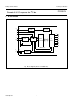
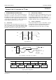
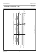
Fig.8 Simplified schematic diagram of each I/O.
handbook, full pagewidth
MBD977
DQ
C
I
S
FF
DQ
C
I
S
FF
100
µA
to interrupt
logic
V
SS
P0 to P7
V
DD
write pulse
data from
shift register
power-on
reset
read pulse
data to
shift register
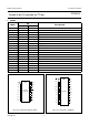
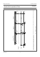
Fig.9 PCF8574 and PCF8574A slave addresses.
handbook, full pagewidth
MBD973
S 0 1 0 0 A2 A1 A0 0 A 1 0
slave address
slave address
A
S 0 1 1 A2 A1 A0
a. b.
(a) PCF8574.
(b) PCF8574A.
Each of the PCF8574’s eight I/Os can be independently
used as an input or output. Input data is transferred from
the port to the microcontroller by the READ mode
(see Fig.11). Output data is transmitted to the port by the
WRITE mode (see Fig.10).