
Data Sheet

DS18B20
10 of 27
1-WIRE BUS SYSTEM
The 1-Wire bus is a system which has a single bus master and one or more slaves. The DS18B20
behaves as a slave. The discussion of this bus system is broken down into three topics: hardware
configuration, transaction sequence, and 1-Wire signaling (signal types and timing).
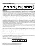
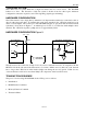
HARDWARE CONFIGURATION
The 1-Wire bus has only a single line by definition; it is important that each device on the bus be able to
drive it at the appropriate time. To facilitate this, each device attached to the 1-Wire bus must have open
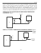
drain or 3-state outputs. The 1-Wire port of the DS18B20 (DQ pin) is open drain with an internal circuit
equivalent to that shown in Figure 9. A multidrop bus consists of a 1-Wire bus with multiple slaves
attached. The 1-Wire bus requires a pullup resistor of approximately 5 kΩ.
HARDWARE CONFIGURATION Figure 9
The idle state for the 1-Wire bus is high. If for any reason a transaction needs to be suspended, the bus
MUST be left in the idle state if the transaction is to resume. Infinite recovery time can occur between
bits so long as the 1-Wire bus is in the inactive (high) state during the recovery period. If this does not
occur and the bus is left low for more than 480 µs, all components on the bus will be reset.
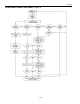
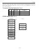
TRANSACTION SEQUENCE
The protocol for accessing the DS18B20 via the 1-Wire port is as follows:
Initialization
ROM Function Command
Memory Function Command
Transaction/Data
+3V - +5V
4.7K
BUS MASTER
R
X
T
X
DS18B20 1-WIRE PORT
5 µA
T
yp
.
R
X
T
X
100 OHM
M
OS
FET
R
X
= RECEIVE
T
X
= TRANSMIT