
Data Sheet

PCF8563_5 © NXP B.V. 2007. All rights reserved.
Product data sheet Rev. 05 — 17 July 2007 9 of 32
NXP Semiconductors
PCF8563
Real time clock/calendar
7.6.4 Alarm registers
When one or more of these registers are loaded with a valid minute, hour, day or weekday
and its corresponding bit Alarm Enable (AE) is logic 0, then that information will be
compared with the current minute, hour, day and weekday. When all enabled comparisons
first match, the Alarm Flag (AF) is set. AF will remain set until cleared by software.
Once AF has been cleared it will only be set again when the time increments to match the
alarm condition once more. Alarm registers which have their bit AE at logic 1 will be
ignored.
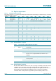
July Cxx00111
August C x x 01000
September C x x 01001
October C x x 10000
November C x x 10001
December C x x 10010
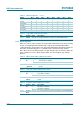
Table 15. Years (address 08h) bits description
Bit Symbol Value Description
7 to 0 YEARS 00 to 99 this register holds the current year coded in BCD format
Table 14. Month assignments
…continued
Month Bit 7 Bit 6 Bit 5 Bit 4 Bit 3 Bit 2 Bit 1 Bit 0
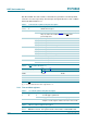
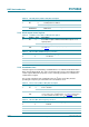
Table 16. Minute alarm (address 09h) bits description
Bit Symbol Value Description
7 AE 0 minute alarm is enabled
1 minute alarm is disabled
6 to 0 ALARM
_MINUTES
00 to 59 this register holds the minute alarm information coded in BCD
format
Table 17. Hour alarm (address 0Ah) bits description
Bit Symbol Value Description
7 AE 0 hour alarm is enabled
1 hour alarm is disabled
5 to 0 ALARM_
HOURS
00 to 23 this register holds the hour alarm information coded in BCD
format
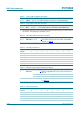
Table 18. Day alarm (address 0Bh) bits description
Bit Symbol Value Description
7 AE 0 day alarm is enabled
1 day alarm is disabled
5 to 0 ALARM_
DAYS
01 to 31 this register holds the day alarm information coded in BCD format