
Data Sheet

PCF8563_5 © NXP B.V. 2007. All rights reserved.
Product data sheet Rev. 05 — 17 July 2007 7 of 32
NXP Semiconductors
PCF8563
Real time clock/calendar
Bits TIE and AIE: These bits activate or deactivate the generation of an interrupt when
TF or AF is asserted, respectively. The interrupt is the logical OR of these two conditions
when both AIE and TIE are set.
[1] TF and INT become active simultaneously.
[2] n = loaded countdown value. Timer stopped when n = 0.
7.6.3 Time and date registers
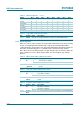
Table 5. Control/status 2 (address 01h) bits description
Bit Symbol Value Description
7 to 5 0 default value is logic 0
4 TI/TP 0
INT is active when TF is active (subject to the status of TIE)
1
INT pulses active according to Table 6 (subject to the status of
TIE); note that if AF and AIE are active then
INT will be
permanently active
3 AF 0 (read) alarm flag inactive
1 (read) alarm flag active
0 (write) alarm flag is cleared
1 (write) alarm flag remains unchanged
2 TF 0 (read) timer flag inactive
1 (read) timer flag active
0 (write) timer flag is cleared
1 (write) timer flag remains unchanged
1 AIE 0 alarm interrupt disabled
1 alarm interrupt enabled
0 TIE 0 timer interrupt disabled
1 timer interrupt enabled
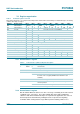
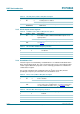
Table 6.
INT operation (bit TI/TP = 1)
Source clock (Hz) INT period (s)
[1]
n=1
[2]
n>1
4096 1⁄8192 1⁄4096
64 1⁄128 1⁄64
11⁄64 1⁄64
1⁄60 1⁄64 1⁄64
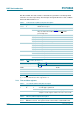
Table 7. Seconds/VL (address 02h) bits description
Bit Symbol Value Description
7 VL 0 clock integrity is guaranteed
1 integrity of the clock information is no longer guaranteed
6 to 0 SECONDS 00 to 59 this register holds the current seconds coded in BCD format;
example: seconds register contains x101 1001 = 59 seconds
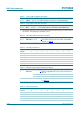
Table 8. Minutes (address 03h) bits description
Bit Symbol Value Description
6 to 0 MINUTES 00 to 59 this register holds the current minutes coded in BCD format