Preface About SunFounder SunFounder is a technology company focused on Raspberry Pi and Arduino open source community development. Committed to the promotion of open source culture, we strive to bring the fun of electronics making to people all around the world and enable everyone to be a maker. Our products include learning kits, development boards, robots, sensor modules and development tools. In addition to high quality products, SunFounder also offers video tutorials to help you make your own project.
Content Components ........................................................................................................................................1 i. Acrylic Plates ..........................................................................................................................1 ii. Mechanical Fasteners...........................................................................................................3 iii. Electrical Components...................................................
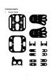
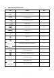
Components i.
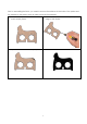
Prior to assembling the Sloth, you need to remove the residues in the holes of the plates and the stickers on the plates. Here we take one plate for example. 1. The sticker is pasted on both sides of 2. Use a Phillips Screw Driver to help scrape the each acrylic plates. edge of the sticker. 3. Rip off the sticker on the acrylic plate 4. Remove the sticker on other side.
ii. Mechanical Fasteners Parts Name Qty M1.2*4 Self-tapping Screw 8 M1.4*10 Screw 4 M2*4 Self-tapping Screw 4 M2*8 Screw 12 M3*6 Screw 12 M3*8 Screw 12 M1.
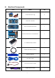
iii.
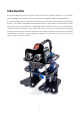
Introduction This cute learning kit focuses on the popular open source platform Arduino. You can learn the knowledge of the Arduino servo and ultrasonic ranging module by applying this kit. It is a new mobile robot called Sloth developed by SunFounder. Each leg has 2 joints driven by servo. Two 18650 chargeable lithium batteries are to supply the bot when the SunFounder Nano is used as the control board, compatible with the Arduino Nano.
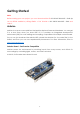
Getting Started Note: Before starting your own project, you must download the file DIY 4-DOF Robot Kit - Sloth.zip on our official website by visiting LEARN -> Get Tutorials -> DIY 4-DOF Robot Kit - Sloth and unzip it. Arduino Arduino is an open source platform that applies simple software and hardware. You can get it in a short even when you know little of it. It provides an integrated development environment (IDE) for code editing and compiling, compatible with multiple control boards.
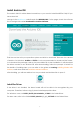
Install Arduino IDE The code in this kit is written based on Arduino, so you need to install the IDE first. Skip it if you have done this. Now go to the arduino.cc website and click DOWNLOAD. On the page, check the software list on the right side under Download the Arduino Software. Find the one that suits your operation system and click to download. There are two versions of Arduino for Windows: Installer or ZIP file. You're recommended to download the former.
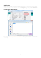
Add Libraries Libraries are a collection of code that makes it easy for you to connect to a sensor, display, module, etc. In this kit, you will need to include NewPing library under path DIY 4-DOF Robot Kit - Sloth\Library to Arduino/libraries. Then you will see “Library added to your libraries”, indicating the library has been included successfully.
Test for Servos and Ultrasonic Module Before assembling, you need to test the servos and the ultrasonic module according to the following steps. i. Servo Test First please test the servo, insert the SunFounder Nano board into the servo expansion board. Pay attention the USB port should be at the same side with blue power supply terminal. Connect the Nano board to computer with a USB cable, you can see a notification in system tray.
In the code, the servo is set to be connected to pin 9 of the servo control board, thus change the 9 to 16 in the code. Fix the wires of battery holder to the power supply terminal, and insert the batteries in holder. Please prepare a servo and a 1-arm rocker arm, then mount the rocker arm onto the servo. Connect the servo to pin 9. Pay attention to the wires, the yellow one connects to S, red one to V, and the brown one to G.
Select the right board to Nano board in IDE. Then select the right port and upload the sketch.
Press the power button on the servo control board. You will see the rocker arm rotates within 0-180 degrees, indicating the servo can work. Then press the power button again to turn it off. Test the other three servos in the same way.
ii. Ultrasonic Test Connect the ultrasonic connecting cable to the ultrasonic module, it has an anti-reversing port. Here the 4 pins are marked with labels on the modules. If you receive the ultrasonic module as shown below, The ultrasonic module as shown below have the same 4 pins of VCC, GND, TRIG, and ECHO with the above one, the method of utilizing is same. But the text-transform of these pins and the order are different.
And connect the pin TRIG to pin 12 of the servo control board. ECHO to pin 11, VCC to V and GND to G. Upload the program to the Nano board, open the serial monitor. Then press the power button on the servo control board. Set the baud rate as 115200, hold the ultrasonic module and make the two ultrasonic “eyes” facing an obstacle, move the robot back and forth, and observe the data shown on serial monitor. If the data changes with the robot’s moving, it proves the ultrasonic module is good.
15
Assembly i. Riband Assembly Before assembling, we define the side with two rectangle slots as the robot head side, place this side as shown. Check the two sets slant-displayed holes, if they are at right side, the plate is at front side, then vice versa. Cut the riband into two pieces nearly equally, and thread them underneath the battery fixing plate, spare some riband at one end so as to take out the battery with the riband underneath. You can skip this step if you feel unnecessary.
ii. Electrical Module Assembly Fix the battery holder underneath the battery fixing plate, pay attention that the end without wires should be in the same side with the robot head. Insert two M3*8 screws through the holes and fasten with M3 nuts. Then press the riband onto the holder, align the positive and negetive poles of the battery with the holders. Cut the riband accordingly.
Put the servo control board onto the M3*6+6 Single-pass aluminum standoffs (on the other opposite side of battery holder), align the holes of them and fasten with M3*6 screws. Then fix the wires of battery holder to the power supply terminal. Note: Make sure the servo control board direction is shown as below: iii. Servo Assembly Put the servo into the slot of the servo fixing plate and hold it. Then insert the M2*8 screws from underneath the hole and fasten with an M2 nuts.
After assembling the two servos, mount the servo fixing plate onto the battery fixing plate, fasten them with M3 *8 screws. Pay attention to insert the servo with its shaft far away from the head side.
How to distinguish the left and right foot: If the curve is at left side, it’s a left foot; if at right, it’s a right one. Insert the bulges of the lower servo fixing plate into holes of the right foot plate. Put M3 nuts in the holes of the fixing plate, insert M3*8 Countersunk Screw into the hole of the foot plate and tighten it. Fix the other lower servo fixing plate onto the right foot in the same way.
Two feet assembly is completed now. Pay attention to the servo shaft’s direction. Insert the 2-arm rocker arm into the hole of the fixing plate, spin the arm in parallel with edge of the plate. And roughly measure the length of them. Cut off the excess of the arm accordingly, and put it back onto the fixing plate. Align the holes on both, and fasten with two M1.2*4 self-tapping screws.
Fix the other rocker arm onto the other fixing plate in the same way. Put the 1-arm rocker arm of a servo onto the fixing plate. Align the holes and fasten with two M1.2*4 self-tapping screws. Fix the rocker arm of the other lower servo onto the other fixing plate in the same way. Prepare the following three sets. Insert the bulges of the ① fixing plate into the concaves of the ③ fixing plate. Keep the rocker arm outward of the ① plate, put two M3 nuts into the slot of the ① and ② plate.
So you’ll get a bridge-shape part, assemble the other “bridge” in the same way. Make sure the rocker arms are on the outside of the plate. iv. Servo INSTALL Test Connect the upper-right servo to port 9, the yellow cable to the signal pin, red to the positive pole and brown to the negative pole. Then connect the lower-right servo, the upper-left one and the lower-left servo to pin 10, 11 and 12 respectively in the same way.
Connect the Nano board and the computer with a USB cable. Open the program simple_robot.ino, and upload the program to the board. Now, it’s in install process. Then power on the robot, keep the power on and the servo connect to the board.
v. Foot Assembly Put the assembled rocker arm fixing plate onto the upper servo, and fasten them with the built-in self-tapping screws. Try to keep the edge of the two plates parallel with each other. If they are not parallel to each other, you need to remount, and don’t rotate them after mounting. Insert the M3*6 Hollow Rivet into the rocker arm fixing plate of the upper servo from the inside. Insert the lower servo into the rocker arm and fasten them with a self-tapping screw.
Fix the other foot in the same way. Insert the bearing into its fixing plate and cover the corn rivet with the bearing. Insert the bulges of the bearing fixing plate into the holes of the foot plate.
Align the band edge in the plate with the hollow rivet to mount. Make sure the band edge side faces inward. Put two M3 nuts into the holes of the bearing fixing plate and hold them. Then insert two M3*8 Countersunk Screws into the holes of the foot plate and tigten them. vi. Head Assembly Assemble the head, insert the ultrasonic module into the ultrasonic fixing plate, and fasten the module with four M1.4*8 screws and nuts.
Put an M3 nuts into the slot of the ultrasonic fixing plate, insert an M3*8 screw into the battery fixing plate and fasten them. vii. Servo CALIBRATION Test Open the program and go to Line 39, disable the INSTALL and activate the CALIBRATION. Select the correct board and port, then upload the sketch. If the robot is not set right, change the angle and upload the code until it is.
Tips for calibration: 1) If the right leg is toe out, you need to decrease the upper-right servo’s angle; if it is toe in, you need to increase the angle. 2) The calibration method for the left leg works the opposite way for right leg. 3) If the right foot’s sole faces outward, you need to decrease the lower-right servo’s angle; if its sole faces inward, you need to increase the angle. 4) The calibration method for the left foot works the opposite way for right foot.
Thus we can calibrate as follows: ① Decrease the upper-right servo’s angle Change 95 degrees to 90 (array_cal[0]: is the upper-right servo’s rotation angle); ② Increase the upper-left servo’s angle Change 115 degrees to 120 (array_cal[2]: is the upper-left servo’s rotation angle); ③ Decrease the lower-right servo’s angle Change 100 degrees to 90 (array_cal[1]: is the lower-right servo’s rotation angle); ④ Increase the lower-left servo’s angle Change 95 degrees to 100 (array_cal[3]: is the lower-left serv
Change code in line 15 to array_cal[4] = {80, 80, 120, 110}; Then click Upload. Observe the four servos to make sure they are in proper angle, then the servo calibration is completed. You can do fine tuning with value changing of “1” each time, if there is a little deviation. Since the servo angles on legs and feet differ, the final calibrated angles (array_cal[4]) will be different too. It will take multiple times of calibration, you should adjust in patience. viii.
Connect pin TRIG of the ultrasonic to pin 4 of the board, ECHO to pin 3, VCC to VCC and GND to GND. ix. Servo RUN Test Go to Line 39 again, disable the CALIBRATION line. Activate the operating programe “run” and burn the program to the board.
After burning successfully, unplug the USB cable and press the power button on the servo control board. You will see the robot moving forward. When encountering an obstacle, it will make a turn and then go forward again. x. Cable Pipe Assembly Bind the servo wires and the ultrasonic connecting cable with a cable pipe.
So far the robot has been assembled successfully, it’s easy if you follow our steps closely. Hope you enjoy the fun of the bot, thanks for watching. Q&A Q1: How can we know the servo is damaged? A1: In Servo Test step, if the servo rocker arm shake, get stuck or can not rotate smoothly, with an abnormal sound, we can judge it as a damaged one.
servos rotating speed in “moving backward”; “delay_Forward”, “delay_Back” are the delays between two moving forward loops and moving backward loops. a) If rebooting happens in moving forward actions, you can decrease the value of “vel” or/ and increase the value of “delay_Forward”. For example, decrease “vel” value to 10, and increase “delay_Forward” to 1500. b) If rebooting happens in mocing backward actions, you can decrease “vel_Back” or/ and increase “delay_Backward”.
change thevalue of vel and delay_Forward in line12 and 13 to as shown: vel = 50, delay_Forward = 500 Then click Upload. Note: If you adjust the robot to a high walking speed, it may fall down and break. Thus it’s better to do some protection for the Sloth. Q4: Sloth walks too slowly when it moves backward. How to solve this? A4: Considering the structure of Sloth, it’s better do adjust a slow speed for backward walking. If you wan to adjust the walking speed, refer to Q3 to adjust the value.
Summary In this manual, having learned the related components for building the robot kit, you’ve gone through the assembly of the mechanical parts and electrical modules with the knowledge of Arduino as well as a brief introduction of the key parts like servo, ultrasonic, etc. Also you’ve got a lot of software and coding, which lays a solid foundation for your futrue journey of exloring open-source field.