Preface About SunFounder SunFounder is a technology company focused on Raspberry Pi and Arduino open source community development. Committed to the promotion of open source culture, we strive to bring the fun of electronics making to people all around the world and enable everyone to be a maker. Our products include learning kits, development boards, robots, sensor modules and development tools. In addition to high quality products, SunFounder also offers video tutorials to help you build your own project.
Contents Components List .................................................................................................................................. 1 Notice .................................................................................................................................................... 8 Lesson 1 Hall Sensor ........................................................................................................................... 10 Lesson 2 RGB LED ...............................
Lesson 27 Flame Sensor..................................................................................................................... 69 Lesson 28 Relay Module ................................................................................................................... 71 Lesson 29 Joystick PS2 ....................................................................................................................... 73 Lesson 30 MQ-2 Gas Sensor........................................................
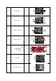
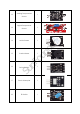
Components List Qty. 1 Analog Hall Sensor 2 2 Switch Hall Sensor 1 3 RGB LED 2 4 Component r Name Su n Fo un de No.
1 6 Knock Sensor 1 7 Infrared Transmitter 1 8 Laser Transmitter Su n 9 r Shock Switch Fo un de 5 1 Reed Switch 1 10 Mini Reed 1 11 Infrared Receiver 1 2
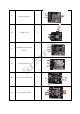
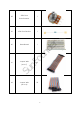
12 Analog Temperature 1 Sensor 13 Digital Temperature 1 Sensor Active Buzzer 15 Passive Buzzer 1 Su n 16 Fo un de r 14 1 Button Switch 1 17 Photo-interrupter 1 18 Tilt Switch 1 3
Mercury Switch 1 20 Magic Cup 2 21 Fo un de r 19 DS18B20 Temperature Sensor 1 Rotary Encoder 1 23 7-color Auto-flash LED 1 24 Photoresistor Sensor 1 Su n 22 4
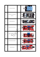
25 26 Humiture Sensor Obstacle Avoidance 1 1 Sensor 28 Microphone Sensor Su n 29 1 r Tracking Sensor Fo un de 27 High-sensitive Voice 1 1 Sensor 30 Metal Touch Sensor 1 31 Flame Sensor 1 5
1 33 Joystick PS2 1 34 MQ-2 Gas Sensor 1 35 LCD1602 37 Su n 36 r Relay Module Fo un de 32 1 4x4 Keypad 1 Remote Control 1 6
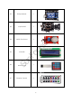
38 250k Ohm 1 470k Ohm Resistor 1 40 Breadboard 1 41 Fo un de 39 Jumper Wire 40 Su n (M to F) r Potentiometer 42 Jumper Wire (M to M) 20 7
Notice All the experiments in this kit are done with SunFounder Uno R3 board, but they are also compatible with SunFounder Mega 2560, SunFounder Nano and all official Arduino Boards. All the code included in this kit works with these boards. So what does COMPATIBLE mean here? It means you can use any of the three boards to do the same experiment with the same wiring. Take turning on an LED as an example.
9 r Fo un de Su n
Lesson 1 Hall Sensor Introduction Based on the Hall Effect, a hall sensor is one that varies its output voltage in response to a magnetic field. Hall sensors are used for proximity switching, positioning, speed detection, and current sensing applications. Hall sensors can be categorized into linear (analog) Hall sensors and switch Hall sensors. A switch Hall sensor consists of voltage regulator, Hall element, differential amplifier, Schmitt trigger, and output terminal and it outputs digital values.
Components - 1 * SunFounder Uno board - 1 * USB data cable - 1 * Hall sensor module - 1 * LCD1602 - 1 * Potentiometer - Several jumper wires Experimental Principles Hall Effect Hall Effect is a kind of electromagnetic effect. It was discovered by Edwin Hall in 1879 when he was researching conductive mechanism about metals. The effect is seen when a conductor is passed through a uniform magnetic field.
Experimental Procedures For linear Hall sensor module, please take the following steps.
For Switch Hall Sensor module Step 1: Build the circuit Switch Hall Sensor Module SunFounder Uno S ----------------------------------------Digital 8 - ---------------------------------------- GND + ---------------------- ----------------- 5V Step 2: Program (Please refer to the example code in LEARN -> Get Tutorial on our website) Step 3: Compile Step 4: Upload the sketch to SunFounder Uno Now, place a magnet close to the switch Hall sensor.
For linear Hall sensor module (with a comparator added) Step 1: Build the circuit Linear Hall Sensor Module SunFounder Uno AO ------------------------------------------- A0 DO ------------------------------------------- Digital 8 - -------------------------------------------- GND + ---------------------------------------------- 5V LCD1602 connection: connect pin RS to digital pin 3; R/W to GND; E to digital pin 4; D4~D7 to digital pin 9 to 12; VSS to GND; VDD to 5V; A to 3.
Lesson 2 RGB LED Introduction There are two kinds of packages for RGB LED (as shown below) in this kit. One is Surface r Mount Device (SMD) type, and the other is Dual In-line Package (DIP) type. - 1 * SunFounder Uno board - 1 * USB data cable - 1 * RGB LED module - Several jumper wires Experimental Principle Fo un de Components RGB LED modules can emit various colors of light. Three LEDs of red, green, and blue are packaged into a transparent or semitransparent plastic shell with four pins led out.
at any given time. Voltage or current source is applied to an analog load in the form of ON or OFF repetitive pulse sequence. When it is on, DC power supply will be applied to the load; when it is off, DC power supply will be disconnected. If only the bandwidth is wide enough, any analog value can be encoded by PWM. The output voltage value is calculated by the Fo un de r on and off time. Vout = (Ton/ T)*Vmax. We can see from the top oscillogram that the amplitude of DC voltage output is 5V.
2. Period describes the reciprocal of pulses in one second 3. Upwm describes the mean value of output voltage (e.g. 0V-5V) Here we input any value between 0 and 255 to the three pins of the RGB LED to make it flash different colors. RGB LEDs can be categorized into common anode type and common cathode type. In this experiment, we use common cathode RGB LED.
Lesson 3 Dual-color Common-Cathode LED Introduction There are two kinds of dual-color Common-Cathode LED in this kit. The only difference is the package size of the LED, as shown below: r Components - 1 * USB data cable Fo un de - 1 * SunFounder Uno board - 1 * Dual-color Common-Cathode LED module - Several jumper wires Experimental Principle Control the LED brightness by the digital port. The color of the LED changes from yellow to red as well as flashes a mixed color.
Su n Fo un de r Now, you can see the dual-color LED flashing yellow, red, and mixed colors.
Lesson 4 Shock Switch Introduction A shock switch (as shown below), also vibration switch, spring switch or shock sensor, is an electronic switch which senses vibration amplitude and transfers the signals to circuit device thus switching on the circuit. It composes of conductive vibration spring, switch, trigger pin, Components - 1 * SunFounder Uno board - 1 * USB data cable - 1 * Shock switch module - Jumper wires Experimental Principle Fo un de r packaging agent and so on.
Step 2: Program (Please refer to the example code in LEARN -> Get Tutorial on our website) Step 3: Compile Step 4: Upload the sketch to SunFounder Uno Now, shake the switch module and you will see the LED attached to pin 13 on the SunFounder Su n Fo un de r Uno board light up.
Lesson 5 Knock Sensor Introduction A knock sensor (as shown below) is similar to the shock switch except that it's more sensitive. Components - 1 * SunFounder Uno board - 1 * USB data cable - 1 * Knock sensor module - Several jumper wires Experimental Principle Fo un de r It can feel small amplitude vibration. Su n The principle is similar to that of the shock switch. Connect the knock switch sensor pin S to D3 to build a simple circuit.
Now, knock the sensor and the LED attached to pin 13 on the SunFounder Uno board will Su n Fo un de r light up.
Lesson 6 Infrared Transmitter Introduction An infrared transmitter module (as shown below) is a device that uses 38K modulation signal generated by MCU to emit infrared rays. r Components - 1 * USB data cable Fo un de - 1 * SunFounder Uno board - 1 * Infrared transmitter module - 1 * LCD1602 - 1 * Potentiometer - Several jumper wires Experimental Principle An infrared transmitter is a device applied in remote control.
Potentiometer connection: Connect the middle pin to VO of LCD1602 and any other pin to GND Step 2: Program (Please refer to the example code in LEARN -> Get Tutorial on our website) Step 3: Compile Step 4: Upload the sketch to SunFounder Uno Now, you can see the infrared transmitter emit infrared rays through a camera or your phone camera. At the same time, the LED attached to pin 13 on SunFounder Uno board lights up Su n Fo un de r and a coded value is displayed on the LCD.
Lesson 7 Laser Transmitter Introduction Laser is widely used in medical treatment, military, and other fields due to its good directivity and energy concentration. The Laser Transmitter module (as shown below), as the name - 1 * SunFounder Uno board - 1 * USB data cable - 1 * Laser transmitter module - Several jumper wires Experimental Principle Fo un de Components r suggests, is a one that can emit laser.
Experimental Procedures Step 1: Build the circuit Laser Transmitter Module SunFounder Uno S ----------------------------------------Digital 9 - -------------------------------------- GND + --------------------------------------- 5V Step 2: Program (Please refer to the example code in LEARN -> Get Tutorial on our website) Step 3: Compile Step 4: Upload the sketch to SunFounder Uno Su n Fo un de r Now, you can see the laser transmitter module send out Morse signals.
Lesson 8 Reed Switch Introduction A reed switch (as shown below) is a sensor used to detect the magnetic field. Hall sensors are generally used to measure the speed of smart car and count products on assembly lines. Reed switches are often used to detect the existence of magnetic field. There are two reed switches in this kit: reed switch and mini reed.
breaking the circuit. Therefore, as line switch components function by magnetic signals, they can be used to count stuff, restrict positions and so on. At the same time, it is widely used in a variety of communication devices. In this experiment, since an LED has been attached to pin 13, just connect pin D0 of the reed switch to D8 of the SunFounder Uno board. When the reed switch inducts magnetic field signals, the LED will be on. Otherwise, it will be off.
Mini Reed The experimental procedures are the same as those of Reed Switch. Connect pin S to D2 of the SunFounder board, and you will see the LED attached to pin 13 light up when a magnet Su n Fo un de r approaches the mini reed.
Lesson 9 Infrared-Receiver Introduction An infrared-receiver is a component that receives infrared signals and can independently receive infrared ray and output signals compatible with TTL level. It's similar with a normal plastic-packaged transistor in size and it is suitable for all kinds of infrared remote control and Components - 1 * SunFounder Uno board - 1 * USB data cable Fo un de r infrared transmission.
Now, press Power on the remote control and the LED attached to pin 13 on the SunFounder Su n Fo un de r Uno board will light up. If you press other keys, the LED will go out.
Lesson 10 Analog Temperature Sensor Introduction A thermistor is the core component of an analog temperature sensor (as shown below). r Components - 1 * USB data cable Fo un de - 1 * SunFounder Uno board - 1 * Analog Temperature Sensor module (thermistor) - 1 * LCD1602 - 1 * Potentiometer - Several jumper wires Experimental Principle This module is based on thermistor principle, whose resistance varies significantly with Su n ambient temperature changes.
Step 2: Program (Please refer to the example code in LEARN -> Get Tutorial on our website) Step 3: Compile Step 4: Upload the sketch to SunFounder Uno Now, touch the thermistor and you can see the current temperature displayed on the LCD Su n Fo un de r in both Celcius and Fahrenheit degrees.
Lesson 11 Digital Temperature Sensor Introduction Compared with an analog temperature sensor, a digital temperature sensor (as shown below) only adds a digital output. You can adjust the threshold by the potentiometer onside. When the output is higher than the threshold, the sensor will output high level; when it is lower Components - 1 * SunFounder Uno board - 1 * USB data cable Fo un de r than the threshold, the sensor will output low level.
Step 2: Program (Please refer to the example code in LEARN -> Get Tutorial on our website) Step 3: Compile Step 4: Upload the sketch to SunFounder Uno Now, touch the thermistor and you will see the LED attached to pin 13 on SunFounder Uno Su n Fo un de r board light up after a while.
Lesson 12 Buzzer Introduction Buzzers can be categorized as active buzzers and passive ones (See the following picture). r Components - 1 * USB data cable - 1 * Buzzer module - Several jumper wires Experimental Principle Fo un de - 1 * SunFounder Uno board Place the pins of two buzzers face up and you can see the one with a green circuit board is a passive buzzer, while the other with a black tape, instead of a board, is an active buzzer, Su n as shown below.
Experimental Procedures Passive Buzzer Step 1: Build the circuit Passive Buzzer Module SunFounder Uno S ------------------------------------- D11 - ------------------------------------ GND + -------------------------------------- 5V Step 2: Program (Please refer to the example code in LEARN -> Get Tutorial on our website) Step 3: Compile Step 4: Upload the sketch to SunFounder Uno Su n Fo un de r Now, you can hear the passive buzzer beep for warning.
Active Buzzer Note: The active buzzer has built-in oscillating source, so it will beep as long as it is electrified, but it can only beep with a fixed frequency.
Lesson 13 Button Switch Introduction Most SunFounder boards already have an LED attached to pin 13 itself. So we r will use a button module and this LED to build a simple circuit and make an LED brighten. - 1 * SunFounder Uno board - 1 * USB data cable - 1 * Button module - Several jumper wires Experimental Principle Fo un de Components With the LED attached to pin 13, connect the button module to digital pin 8. When the button Su n module inducts button-pressing signals, the LED will be on.
Now, press the button and the LED attached to pin 13 on the SunFounder Uno board will light Su n Fo un de r up.
Lesson 14 Photo-interrupter Introduction A photo-interrupter is a sensor that arranges light-emitting component and light-receiving component face-to-face and packages them together. It applies the principle that light is interrupted when an object passes through the sensor. Therefore, photo-interrupters are Components - 1 * SunFounder Uno board - 1 * USB data cable Fo un de r widely used in speed measurement.
Now, stick a piece of paper in the gap of the sensor, and the LED attached to pin 13 on the Su n Fo un de r SunFounder Uno will go out; remove the paper, and then the LED will light up again.
Lesson 15 Tilt-Switch Introduction The tilt switch sensor module is a ball tilt switch with a metal ball inside. It is used to detect inclinations of a small angle. r Components - 1 * USB data cable - 1 * Tilt-switch module - Several jumper wires Experimental Principle Fo un de - 1 * SunFounder Uno board Apply the principle that the ball in the switch moves with different angles of inclination to make triggering circuits. The tilt switch module uses a ball tilt switch with bidirectional conduction.
Step 3: Compile Step 4: Upload the sketch to SunFounder Uno Su n Fo un de r Now, tilt the switch and the LED attached to pin 13 on the SunFounder Uno board will light up.
Lesson 16 Mercury Switch Introduction Similar to a tilt switch, a mercury switch is used to detect slight inclinations of a large angle. A mercury switch (also known as a mercury tilt switch) is a switch which opens and closes an electrical circuit through a small amount of liquid mercury. Mercury switches have one or more sets of electrical contacts in a sealed glass envelope which contains a bead of mercury. The envelope may also contain air, an inert gas, or a vacuum.
Experimental Procedures Step 1: Build the circuit Mercury Switch Module SunFounder Uno S------------------------------------------- D2 - ------------------------------------------ GND + ------------------------------------------ 5V Step 2: Program (Please refer to the example code in LEARN -> Get Tutorial on our website) Step 3: Compile Step 4: Upload the sketch to SunFounder Uno Su n Fo un de r Now, tilt the switch and the LED attached to pin 13 on the SunFounder Uno board will light up.
Lesson 17 Magic Cup Introduction There are two same Magic Cup modules in this kit, and each adds a separate LED based on the mercury switch. You may learn the application of one module and then try to apply two Components - 1 * SunFounder Uno board - 1 * USB data cable - 2 * Magic cup module - Several jumper wires Su n Experimental Principle Fo un de r modules together to make one dim when at the same time the other brightens.
Now, tilt the breadboard and you will see the LED on one module gets dimmer while that on Su n Fo un de r the other LED becomes brighter.
Lesson 18 DS18B20 Temperature Sensor Introduction The Temperature Sensor DS18B20 is a commonly used digital temperature sensor featured with small size, low-cost hardware, strong anti-interference capability and high precision. The digital temperature sensor is easy to wire and can be applied a various occasions after packaging.
LCD1602 connection: connect pin RS to digital pin 4; R/W to GND; E to digital pin 5; D4~D7 to digital pin 9 to 12; VSS to GND; VDD to 5V; A to 3.3V; K to GND Potentiometer connection: Connect the middle pin to VO of LCD1602 and any other pin to GND Step 2: Program (Please refer to the example code in LEARN -> Get Tutorial on our website) Step 3: Compile Step 4: Upload the sketch to SunFounder Uno Su n Fo un de r Now, you can see the value of the current temperature displayed on the LCD.
Lesson 19 Rotary Encoder Introduction A rotary encoder is an electro-mechanical device that converts the angular position or motion of a shaft or axle to an analog or digital code. Rotary encoders are usually placed at the side which is perpendicular to the shaft.
r It is difficult to distinguish between the left turn and right turn when programming. However, Fo un de when using an oscilloscope to observe the left turn and right turn of a switch, you will find a Su n phase difference between the signals of the two output pins as shown below. It shows that if output 1 and output 2 is high, then the switch rotates clockwise; if output 1 is high and output 2 is low, then the switch rotates counterclockwise.
Step 2: Program (Please refer to the example code in LEARN -> Get Tutorial on our website) Step 3: Compile Step 4: Upload the sketch to SunFounder Uno Now, you can see the angular displacement of the rotary encoder printed on Serial Monitor. When you spin the rotary encoder clockwise, the angular displacement increases; when you spin it counterclockwise, the value decreases. Press the switch on the rotary encoder and Su n Fo un de r the value will return to zero.
Lesson 20 7-Color Auto-flash LED Introduction It can automatically flash built-in colors after power on. Components - 1 * SunFounder Uno board - 1 * USB data cable r - 1 * 7-color auto-flash LED module Experimental Principle Fo un de - Several jumper wires When being power on, the 7-color auto-flash LED will flash built-in colors. Experimental Procedures Just connect pin S to 5V of the SunFounder Uno board and pin - to GND. Su n Now, you can see the 7-color auto-flash LED flashing seven colors.
Lesson 21 Photoresistor Sensor Introduction The sensor is in fact a photoresistor which changes its resistance with varying light intensity. It can be used to make a photoswitch. - 1 * USB data cable Fo un de - 1 * SunFounder Uno board r Components - 1 * Photoresistor sensor module - Jumper wires Experimental Principle A photoresistor or light-dependent resistor (LDR) or photocell is a light-controlled variable resistor.
Step 2: Program (Please refer to the example code in LEARN -> Get Tutorial on our website) Step 3: Compile Step 4: Upload the sketch to SunFounder Uno Now, cover the photoresistor with a cloth or your palm to change the light intensity, and you Su n Fo un de r will find the value displayed on the LCD changes accordingly.
Lesson 22 Humiture Sensor Introduction The digital temperature and humidity sensor DHT11 is a composite sensor that contains a calibrated digital signal output of temperature and humidity. The technology of a dedicated digital modules collection and the temperature and humidity sensing technology are applied to ensure that the product has high reliability and excellent long-term stability.
returns an answer signal. Then the host receives the answer signal and begins to receive 40bit humiture data (8-bit humidity integer + 8-bit humidity decimal + 8-bit temperature integer + 8-bit temperature decimal + 8-bit checksum). For more information, please refer to DHT11 datasheet.
Lesson 23 Obstacle Avoidance Sensor Introduction An Obstacle Avoidance Sensor (as shown below) uses infrared reflection principle to detect obstacles. When there is no object in front, infrared-receiver cannot receive signals; when there is an object in front, it will block and reflect infrared light, then infrared-receiver can Components - 1 * SunFounder Uno board - 1 * USB data cable Fo un de r receive signals.
Experimental Procedures Step 1: Build the circuit Obstacle Avoidance Sensor module SunFounder Uno out -------------------------------------- D8 - ---------------------------------------- GND + ---------------------------------------- 5V Step 2: Program (Please refer to the example code in LEARN -> Get Tutorial on our website) Step 3: Compile Step 4: Upload the sketch to SunFounder Uno Now, put an obstacle in front of the Obstacle Avoidance Sensor and the LED attached to Su n Fo un de r pin 13 on the S
Lesson 24 Tracking Sensor Introduction A tracking sensor (as shown below) has the same principle with an obstacle avoidance sensor but has small transmitting power.
Step 2: Program (Please refer to the example code in LEARN -> Get Tutorial on our website) Step 3: Compile Step 4: Upload the sketch to SunFounder Uno Now, draw two black thick lines on the paper. If the rays emitted by the sensor encounter the black lines, the LED attached to pin 13 on SunFounder Uno board will light up. Otherwise, Su n Fo un de r it will go out.
Lesson 25 Microphone Sensor Introduction There are two kinds of microphone sensor in this kit: microphone sensor and high-sensitive voice sensor (as shown below). The only difference between them is sensitivity. In this experiment, we will take the microphone sensor for example. You may try to apply the other sensor based on what you've got during the process.
Fo un de r The schematic diagram: LM393 is a voltage comparator. When the voltage of the in-phase terminal (pin 3) is higher than that of the inverting terminal (pin 2), the output terminal (pin 1) will output high. Otherwise, it outputs low. First, adjust the potentiometer to make the voltage for pin 2 of LM393 less than 5V. When there is no voice input, the resistance of the microphone is very Su n large.
Now, speak near or blow into the microphone, and you can see the LED attached to pin 13 Su n Fo un de r on the SunFounder Uno board brighten.
Lesson 26 Metal Touch Sensor Introduction A metal touch sensor is a type of switch that only operates when it's touched by a charged body. It has a high-frequency transistor which can conduct electricity when receiving electromagnetic signals.
Step 3: Compile Step 4: Upload the sketch to SunFounder Uno Now, touch the base electrode of the transistor and the LED attached to pin 13 on the Su n Fo un de r SunFounder Uno board will light up.
Lesson 27 Flame Sensor Introduction A flame sensor module performs detection by capturing infrared wavelengths from flame. It can be used to detect and warn of flames. Components r - 1 * SunFounder Uno board - 1 * Flame sensor module - Several jumper wires Experimental Principle Fo un de - 1 * USB data cable There are several types of flame sensors. In this experiment, we will use a far-infrared flame sensor. It can detect infrared light with a wavelength ranging from 700nm to 1000nm.
Now, ignite a lighter near the flame sensor, and the LED on the module and that attached Su n Fo un de r to pin 13 on Uno will light up.
Lesson 28 Relay Module Introduction Relays are suitable for driving high power electronic devices such as lights, electric fans and air condition. A relay can be used to control high voltages with a low voltage by connecting Components - 1 * SunFounder Uno board - 1 * USB data cable - 1 * Relay module - Several jumper wires Experimental Principle Fo un de r it to an MCU. Connect IO to the SunFounder Uno board.
Now, you may hear the ticktock. That's the normally closed contact opened and the normally open contact closed. You can attach a high voltage device to the module. For example, connect a bulb of 220V voltage to the output port of the relay module, and then Su n Fo un de r the relay will act as an automatic switch.
Lesson 29 Joystick PS2 Introduction A joystick is an input device consisting of a stick that pivots on a base and reports its angle or direction to the device it is controlling. Joysticks are often used to control video games Components - 1 * SunFounder Uno board - 1 * USB data cable - 1 * Joystick PS2 module - Several jumper wires Experimental Principle Fo un de r and robots. A Joystick PS2 is used here.
Step 2: Program (Please refer to the example code in LEARN -> Get Tutorial on our website) Step 3: Compile Step 4: Upload the sketch to SunFounder Uno Now, push the rocker and the coordinates of X and Y axes displayed on Serial Monitor will Su n Fo un de r change accordingly; press the button, and the coordinate of Z=0 will also be displayed.
Lesson 30 MQ-2 Gas Sensor Introduction Gas Sensor MQ-2 is for flammable gas and smoke detection by measuring concentrations of combustible gases in the air. They are often used for detecting smoke and flammable gasses in households, industry or automobiles.
Step 2: Program (Please refer to the example code in LEARN -> Get Tutorial on our website) Step 3: Compile Step 4: Upload the sketch to SunFounder Uno Now, ignite a lighter or light a candle and release a small amount of smoke or gases into a flask (or other glass containers). Then place the sensor over the container, or invert the container and place the sensor at the mouth. When the concentration reaches the threshold, Su n Fo un de r you can see the value displayed on Serial Monitor change.
Lesson 31 Password Lock Introduction After having learnt so many independent modules, let’s use several together to make some comprehensive experiments. In this lesson, we use an LCD1602, a relay module, a potentiometer and a keypad to assemble a simple password lock. The circuit is controlled by the SunFounder Uno board and can be applied in security door.
Step 2: Program (Please refer to the example code in LEARN -> Get Tutorial on our website) Fo un de Step 4: Upload the sketch to SunFounder Uno r Step 3: Compile Now, the LCD will show "Welcome" after power on. When you press the * key, it will prompt "Input Your Code:". If you input 123456 and press # key to confirm, "Input Correctly Please Come In" will be displayed and the LED will light up.
Lesson 32 Lie Detector Introduction How can an Evil Genius be sure that their prisoners are telling the truth? By a lie detector, of course. This lie detector uses an effect known as galvanic skin response. As a person becomes nervous – for example, when telling a lie – their skin resistance decreases. We can measure this resistance using an analog input and use an LED and buzzer to indicate an untruth.
Step 2: Program (Please refer to the example code in LEARN -> Get Tutorial on our website) Step 3: Compile Step 4: Upload the sketch to SunFounder Uno To test the lie detector, you might need a test subject, as you will need one hand free to adjust the knob of the potentiometer. Now ask your test subject to side down. First, let him/her touch the other end of the two jumper wires with two adjoining fingers. Then spin the knob of the pot until the LED turns green. You may now "interrogate" the subject.
Lesson 33 Fire Alarm Introduction With the increasing use of fire and electricity in household, home fire accidents occur more and more frequently. Thus, fire alert plays a more important role in people's life. In this lesson, we will use a gas sensor, a flame sensor and a passive buzzer module to assemble a fire alarm.
Now, ignite a lighter near the sensor and you can see the LED attached to pin 13 light up Su n Fo un de r and the buzzer beeps.
Lesson 34 Thermostatic Water Tank System Introduction In this lesson, we will use a Rotary Encoder module, an Analog Temperature Sensor module, a Relay module, a Button module and an I2C LCD1602 to build a Thermostatic Water Tank system.
Step 2: Program (Please refer to the example code in LEARN -> Get Tutorial on our website) Step 3: Compile Step 4: Upload the sketch to SunFounder Uno Now, after start up, you will see "Thermostatic Water Tank" displayed on the LCD1602, and then current temperature in both Celsius and Fahrenheit degrees. Press the button to setup. Then spin the knob of the rotary encoder to change the temperature threshold. After setting is finished, for example, to 30℃, press the rotary encoder to confirm.
Lesson 35 Intelligent Environment Monitoring Introduction In this lesson, we will use a humiture sensor module, a DS18B20 module, an infrared receiver module, a high-sensitive voice sensor module, a photoresistor module, an analog-hall sensor module, an LCD1602 and a remote control to build an intelligent environment monitoring system.
Photoresistor module connection: connect pin S to analog port A1, pin - to GND, and + to 5V Analog-hall sensor module connection: connect pin S to analog port A2, pin - to GND, and + to 5V Step 2: Program (Please refer to the example code in LEARN -> Get Tutorial on our website) Step 3: Compile Step 4: Upload the sketch to SunFounder Uno Now, press "Power" Key and you can see "Environment Monitor Begin:" on the LCD. Press digital 1 key and it will show "DS18B20" and a temperature value.
For Safe Use All parts and devices in this kit should be powered appropriately in compliance with relevant regulations and standards applicable in the country of intended use. The connection of unapproved external devices to the modules/boards in this kit may affect compliance or result in damage to the unit, for which we will not be responsible.