
Product Manual A

8300GA: Parts Breakdown and Operating Manual 3 rev: 11/14/07
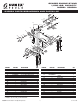
ASSEMBLY INSTRUCTIONS
Assembleasshowninthediagram.1First,installthecasters(5&16)tothefrontandrearaxles(2&18)usingthe
hardwareitems3,4&6,beingsuretoinsertboltsfromthebottomsideofcasterplate.IMPORTANT: All hardware
that assembles items 2, 9, 18, 19 & 27 together should be assembled loose to ensure all bolts fit
through their designated holes. 2Attachthecenterbeamassembly(9)totheaxleassemblies(2&18)using
hardwareitems1,10,11&17.3Next,attachoneendofbrace(19)tothecenterbeamusinghardwareitems1,10,
and11.Makesurepositionofbraceisasshownindiagram.4PIacepost(27)withgearboxassemblyontobase
assemblyasfollows:Standthepostonthebaseandattachbypassingbolt,item1,throughmiddleholeinthebase
bracketandthehexshapedmountweldedtothebottomofthepost.Thenpasspin,item7,throughtheupperhole
inthebasebracketandjustinfrontofthepost.Securepinwithclip(8)provided.Now,insertpin,item7,throughthe
rearhole,includingbothbracketsandsecurewithclip(8)provided.5Attachtheendofthebrace,item19,tothe
postusingpinandclip,items7&8.6Nowtightenallhardwarethatassemblesitems2,9,18,19and27together.7
Rotatethewormbox(29)soitsthreeholeslineupwiththeholesinthepost(27)andsecurethemwiththehardware
25and26provided.Thewormbox(29)shouldbepositionedasshowninthediagram.8Tofoldenginestand,
simply remove the three pins and clips, fold brace forward, and then fold post forward. The pins and clips can be
stored in open holes.
OPERATING INSTRUCTIONS
ThisisthesafetyalertsymbolusedfortheOPERATINGINSTRUCTIONSsectionofthismanualtoalertyouto
potential personal injury hazards. Obey all instructions to avoid possible injury or death.
NOTE:Donotmountenginetomountingplateunlessallthreepins,item7,areinplaceandsecuredwithnumber8
clipsprovidedaccordingtotheASSEMBLYINSTRUCTIONS.
Consult the vehicle or engine manufacturer for service manuals and or technical bulletins that provide information
on suggested engine mounting tips, proper size and type mounting bolts and the engine’s center of balance. The
engine’s center of balance will have to be aligned with the rotational axis of the engine stand’s mounting head
assembly.
Drainoilandcoolantandremoveclutchbellhousingandywheelfromenginebeforemounting.Attachanengine
lifting bar or sling to the engine and secure the bar or sling to a shop crane or hoist. Slowly lift the engine from its
compartmentmakingsurenoothervehiclecomponents,wiresorhosesobstructthefreemovementoftheengine.
Raise the engine high enough so its center of balance is close to the rotational axis of the stand’s mounting head.
Makesure,thefourmountingheadngersarelooselyconnectedtothemountingheadplate.Securethefour
mountingheadngerstothebellhousingendoftheenginewiththeappropriateboltsandwashers.Reposition
themountinghead,ngersandenginesotheengine’scenterofbalanceiswithinoneinchofthemountinghead’s
rotationalaxis.Tightenallboltstoasufcienttorquerequirementthatpreventsanyslippage.
Slowlylowerthecraneorhoistsotheenginestandsupportsfullweightoftheengine.Tocheckenginebalance
andsecuresetupoftheenginetothestand,slowlyrotatetheenginebyturningthegearcrankhandle.Ifbalance
or setup are not stable, rotate the engine to its original position, raise the crane or hoist so the weight of the engine
isremovedfromthestandandmakethecorrectadjustments.Afteradjustmentsaremade,tightenallbolts.This
adjustment procedure may have to be duplicated several times until correct. After the setup is balanced and secure,
the lifting bar or sling can be removed from crane or hoist.
To remove the engine from the stand, connect the lifting bar or sling to the crane or hoist and raise the engine high
enoughtotaketheweightoffthestand.Carefullyremovetheboltsthatconnectthefourmountingngerstothe
engine.Beawaretherewillbeaslightmovementofstandastotalengineweightistransferredtocraneorhoist.
Thisenginestandhasafoldingfeaturethatcansavespaceormakestorageeasy.Justremovethethreepins(7)
andtheirclips(8)sothebrace(19)andpost(27)cantatontopofthecenterbeamassembly(9).Thepinsand
clips can be stored in the open holes.
GEARED ENGINE STAND
1,000 LBS. CAPACITY
MODEL: 8300GA