
Instructions / Assembly


8035 & 8035R 3 11/23/20
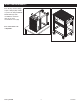
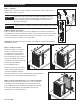
Step 5: Attaching the Handle
Attach the handle (#11) using
the 4 M8x20 handle bolts.
NOTE: The handle should be
assembled on the same side
as the locking casters (#9).
Step 6: The cart is complete.
ASSEMBLY INSTRUCTIONS
6.
5.
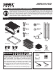
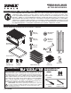
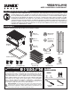
REPLACEMENT PARTS LIST
Item Part # Description # Req’d
1 RS8035RM Rubber Mat (each) 2
2 Sliding Top 1
3 Sliding Top with Lock 1
4 RS8035LGBK Leg (each) (black) 4
RS8035LGR Leg (each) (red)
5 Drawer 2
6 RS8035DH Drawer Handle (each) 2
7 Bottom Tray 1
8 RSFWH 5" Fixed Wheel (each) 2
9 RSSWLCS 5" Locking Caster (each) 2
10 RS8035SL Drawer Slides (pair) for serial 2
numbers ≤20100457-506
RS8035SL2 Drawer Slides (pair) for serial 2
numbers ≥21010001-200
11 RS8035PH Push Handle with Hardware 1
12 RS8035LK Lock with 2 Keys 1
13 RS8035SLT Sliding Top Slides (pair) 1
RS80354LK 4 Pc. Set EVA Liners (not shown) 1
RS8035CBK Caster Bolt Kit (not shown) 1
(set includes 16 M8 x 16 bolts,
32 washers and 16 M8 nuts)
RS8035LBK Leg Bolt Kit (not shown) 1
(set includes 32 M8 x 16 bolts
and 32 M8 washers)
1
2
4
5
6
7
8
13
12
3
11
10
9