
Manual

6609 3 rev. 09/26/08
SETUP
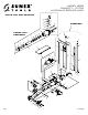
PLEASE REFER TO THE EXPLODED VIEW DRAWING IN THIS MANUAL IN ORDER TO IDENTIFY PARTS.
1. In order to install the handle assembly item #54 in the handle socket item #32, first align the main handle tube with the largest hole in the
handle socket and the lock pin rod with the smaller hole in the handle socket.
2. Make sure the lock pin rod is in the down/lock position before insertion in the handle socket. Once the main handle tube and lock pin rod
are aligned with their respective holes in the handle socket, push the handle assembly in the handle socket so the end of the handle tube
engages the release valve mechanism in the bottom of the handle socket and the lock pin rod engages one of the three (3) locking holes in
the item #1 frame.
3.Nowrotatethe"T"handleportionofthehandleassemblysoitisperfectlyalignedwiththejackbeforetighteningtheitem#36boltanditem
#34 nut. Tighten the bolt and nut so the handle can not rotate. Disengage the lock pin rod by pulling up on the lever and engaging the lever
with the slot in top of the handle assembly. The handle assembly should be free to pump up and down.
4. In order to check for proper handle assembly alignment with the handle socket, see if the lock pin rod will engage with the three locking
holesintheframe.Also,turnthereleasevalveknobatthetopofthehandleassemblyleftandthenrighttoseeifthereleasevalveu-jointin
front and below the handle socket is rotating simultaneously with the turning of the knob.
5. Before Use:Airmaybecometrappedinthehydraulicsystem.
PURGING AIR FROM THE HYDRAULIC SYSTEM:
a. Rotate the knob at the top of the handle assembly in a clockwise direction until tight.
Nowturnitinacounterclockwisedirectiontwofullturns.
b. Activatethefootpumppedalitem#33about15times.
c. Rotate the knob at the top of the handle assembly in a clockwise direction until tight.
d. Activatethefootpumpuntiltheliftarmisraisedtomaximumheight.Youshouldexperienceafullpumpstrokewitheachincremental
pump of the pedal.
e. If it does not feel your are getting full incremental pump stroke at anytime during the pumping operation, repeat steps "a" through "d"
until all air is purged from the system.
OPERATING INSTRUCTIONS
ThisisthesafetyalertsymbolusedfortheOPERATINGINSTRUCTIONSsectionofthismanualtoalertyoutopotentialpersonal
injuryhazards.Obeyallinstructionstoavoidpossibleinjuryordeath.
IMPORTANT: Before attempting to raise any vehicle, check vehicle service manual for recommended lifting surfaces.
OPERATION:
1. To raise load: Turn the knob at the top of the handle assembly in a clockwise direction until tight. Position the jack under the load.
Proceedtopumpthehandleorthefootpedalinordertoraisetheliftarmtotheload.Asthesaddleattheendoftheliftarmgetscloser
to the load, reposition the jack so the saddle will contact the load firmly and the load is centered on the saddle. Make sure the saddle is
correctlypositioned.Rememberthatfootpedalpumpoperationisonlyusedtoquicklyraisethesaddletotheload.Thehandlepump
operation of the jack is used to lift the load. Raise the load to the desired work height. Place jack stands of appropriate capacity at the
vehicle manufacturers's recommended support areas that provide stable support for the raised vehicle. DO NOT CRAWL UNDER
VEHICLE WHILE LIFTING VEHICLE OR REMOVING THE JACK STANDS! Once jack stands are positioned, turn the knob at the top
ofthehandleassemblyVERYSLOWLY.Lowertheloadtorestonthejackstands.Inspecttherelationshipbetweenthejackstandsandload
tomakesurethesetupisstableandsafe.Ifthesetupisnotstableorsafefollowtheprecedingstepsuntilcorrected.NOTE.Oncethehand
pump operation has ceased, the handle assembly can be locked in any of the three (3) handle locking positions. Typically, the handle
locking positions are used for moving the jack around the shop, keeping the handle out of the way or preventing the handle from being
pumped.
2. To lower load:Followtheproceduresmentionedin"Toraiseload"sectionoftheOPERATINGINSTRUCTIONSinordertoraisetheload
off the jack stands. Once the load has cleared the jack stands, remove the stands from under the load and away from the work area. Turn
the knob at the top of the jack's handle assembly very slowly in a counterclockwise direction until the load is completely lowered to the
ground. Once the jack's lifting saddle has cleared the load, remove the jack from under the load.
CAUTION:Keephandsandfeetawayfromthehingemechanismofthejack.
PREVENTATIVE MAINTENANCE
ThisisthesafetyalertsymbolusedforthePREVENTATIVEMAINTENANCEsectionofthismanualtoalertyoutopotentialpersonal
injuryhazards.Obeyallinstructionstoavoidpossibleinjuryordeath.
1. Alwaysstorethejackinawellprotectedareawhereitwillnotbeexposedtoinclementweather,corrosivevapors,abrasivedust,orany
other harmful elements. The jack must be cleaned of water, snow, sand or grit before using.
2. Thejackmustbelubricatedperiodicallyinordertopreventprematurewearingofparts.Ageneralpurposegreasemustbeappliedtoall
zerkgreasettings,casterwheels,frontaxlewheels,elevatorarm,handlebasepivotbolts,releasemechanismandallotherbearing
surfaces.
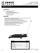
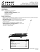
OWNER'S MANUAL
MODEL 6609
CAPACITY: 10 TON
HYDRAULIC SERVICE JACK