AltamarTM • CameoTM • CapriTM • MajestaTM • MarinTM • MaxxusTM • OptimaTM 6530-395S, Rev.
Attention New Hot Tub Owner! Congratulations on the purchase of your new Sundance® hot tub! The following is a list of automated functions performed by your hot tub. These functions are listed below in an attempt to suppress any operational concerns you may have during the first 24-hours of ownership! Also listed below are important maintenance recommendations you should observe on a regular basis to protect your new investment.
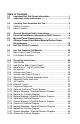
Table of Contents 1.0 2.0 Important Hot Tub Owner Information...................................1 Important safety instructions.................................................2 3.0 3.1 3.2 Locating Your Sundance Hot Tub...........................................6 Outdoor Location........................................................................7 Indoor Location...........................................................................7 4.0 5.0 6.0 7.0 8.0 General Electrical Safety Instructions.
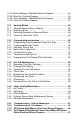
10.23 10.24 10.25 10.26 Marin Massage / Waterfall Selector Diagram...........................44 Marin Air Controls Diagram......................................................45 Capri Massage / Waterfall Selector Diagram...........................46 Capri Air Controls Diagram.......................................................47 11.0 11.1 11.2 11.3 11.4 Heating Modes.......................................................................48 Standard Mode (Factory Default)...............................
19.0 20.0 Export 50Hz Maxxus Electrical Wiring Diagram ................68 Circuit Board Pin Assignments ...........................................69 21.0 Typical Hot Tub Wiring Diagrams A-B . ...............................70 22.0 22.1 22.2 22.3 22.4 22.5 22.6 22.7 22.8 22.9 22.10 Optional SunSound™ Stereo Receiver Features................71 SunSound Stereo Receiver Button Controls............................71 SunSound Stereo Receiver General Controls..........................
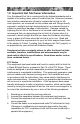
1.0 Important Hot Tub Owner Information Your Sundance® hot tub is constructed to the highest standards and is capable of providing many years of trouble-free use. However, because heat retentive materials are utilized to insulate the hot tub for efficient operation, an uncovered hot tub surface and wall fittings directly exposed to sunlight and high temperatures for an extended period is subject to permanent damage or discoloration.
2.0 Important safety instructions READ AND FOLLOW ALL INSTRUCTIONS CAREFULLY When installing and using this electrical equipment, basic safety precautions should always be followed, including: 1. Warning: To reduce the risk of injury, do not permit children to use this product unless they are closely supervised at all times. 2. Warning: A grounding wire connector is provided on this unit to connect a minimum No. 8 AWG (8.
8. Warning: To Reduce the Risk of Injury: 9. The water in the hot tub should never exceed 104°F (40°C). Water temperatures between 100°F (38°C) and 104°F (40°C) are considered safe for a healthy adult. Lower water temperatures are recommended for young children and when hot tub use may exceed 10 minutes. 10.
box or compartment. To reduce the risk of electric shock, this terminal must be connected to the grounding means provided in the electric supply service panel with a continuous copper wire equivalent in size to the circuit conductors that supply this equipment. *IEC Publication 417, Symbol 5019. 3. At least two lugs marked “Bonding Lugs” are provided on the external surface or on the inside of the supply terminal box/compartment.
WARNING: Do not permit electric appliances (such as lights, telephone, radio, television, etc.) within 5 feet (1.5m) of this hot tub unless such appliances are built-in by the manufacturer. CAUTION: Maintain water chemistry in accordance with manufacturer’s instructions. WARNING: The use of alcohol or drugs can greatly increase the risk of fatal hyperthermia in hot tubs. SAVE THESE INSTRUCTIONS HYPERTHERMIA Prolonged immersion in hot water may induce hyperthermia.
3. 4. 5. 6. 7. 8. Immersion in water in excess of 104°F (40°C) can be hazardous to your health. Observe a reasonable time limit when using the hot tub. Long exposures at higher temperatures can cause high body temperature. Symptoms may include dizziness, nausea, fainting, drowsiness, and reduced awareness. These effects could possibly result in drowning. Do not use the hot tub under the influence of alcohol, narcotics, or other drugs.
equipment and create a wet condition in which it would sit in. For spas which will be recessed into a floor or deck, install so as to permit access to the equipment, either from above or below, for servicing. Make certain that there are no obstructions which would prevent removal of all side cabinet panels and access to the jets components, especially on the side with the equipment bay doors. 3.
• PROPER VENTILATION: Proper ventilation should be discussed with an Engineer or authority competent enough to understand the necessary provisions needed to vent moist or heated air and air associated with chemical odors outdoors. When the spa is in use considerable amounts of moisture will escape potentially causing mold and mildew, over time this can damage certain surfaces and or surroundings.
this point and any ground metal equipment, metal water pipe or conduit within 5 feet (1.5m) of the hot tub, or copper clad grounding rod buried within 5 feet (1.5m) of the hot tub. Bonding wire must be at least No. 8 AWG (8.4mm2) solid copper wire. This is a most important safety assurance feature. Before installing your hot tub, check with your local building department to ensure installation conforms to local building codes. 5.
to comply with Section 422-20 of the National Electrical Code, ANSI/ NFPA 70. The disconnecting means must be readily accessible to the hot tub’s occupant but installed at least 5 feet (1.5m) from hot tub water. 5. The electrical circuit supplied for the hot tub must include a suitable ground fault circuit interrupter (GFCI) as required by NEC Article 680-42. 6.
Figure-A (Maxxus Equipment Area) 12 7 SENTRY SPA CONROLLER 1 4 3 2 11 8 2 10 9 9 1. 2. 3. 4. 5. 6. 7. 6 5 Sentry Control Box Power Supply Entrance(s) Jets Pump #1 Jets Pump #2 Jets Pump #3 Blower Heater 8. Hot Tub Drain (Removable External Drain Cap) 9. Pump Drain Plug(s) 10. Filter/Circulation Pump 11. Optional Subwoofer Behind Bulkhead (Models with Audio Option Only.) 12.
Figure-C Sentry Control Box Figure-D Terminal Block 240V Wire Connection TB1 RY SENT LLER ONRO SPA C Red (L2) 1 TB1 Green 3 4 1. 2. 3. 4.
6.0 Maxxus Power Requirements Sundance® hot tubs are designed to provide optimum performance and flexibility of use when connected to their maximum electrical service.
7.0 Altamar/Cameo/Capri/Marin/Majesta/Optima Power Requirements Sundance hot tubs are designed to provide optimum performance and flexibility of use when connected to their maximum electrical service.
8.0 Hot Tub Fill Up Procedure FOR BEST RESULTS, read each step in its entirety before proceeding with that step. 1. Prepare The Hot Tub For Filling • Clear all debris from the hot tub. (Although the hot tub shell has been polished at the factory, you may want to treat it with a specially formulated hot tub cleaner. Consult your dealer for additional information prior to filling hot tub.
4. Activate Jets Pumps Turn on all jet(s) pumps and blower to ensure proper mixing when adding start up chemical in step 5. 5. Add Start-Up Chemicals Add the hot tub water chemicals as recommended by your Sundance Dealer. See section titled “WATER QUALITY MAINTENANCE”, (page 59) for general guidance. 6. Establish A Stable Sanitizer Reading Establish a stable sanitizer reading between 3.0-4.0 ppm Chlorine or 2.0-4.0 ppm Bromine.
Important Heater Details: • The maximum temperature for which the hot tub can be set is 104°F (40°C) and the minimum is 80°F (27°C). • For Altamar, Cameo, Capri, Optima, Majesta, and Marin hot tubs powered with a 40 amp service, turn off jets pump #1 and jets pump #2 to operate heater. • Setting the thermostat at maximum will not accelerate the heating process. This will only result in a higher ultimate temperature.
Water Fill Volume by Model Hot Tub Model Approximate Fill Volume Altamar....................................... 385 US Gallons (1,457 Liters) Cameo........................................ 450 US Gallons (1,703 Liters) Capri........................................... 215 US Gallons (814 Liters) Majesta....................................... 375 US Gallons (1,420 Liters) Marin........................................... 310 US Gallons (1,173 Liters) Maxxus.......................................
13. Consult your authorized Sundance dealer for chemical recommendations, then add chemicals to hot tub water to achieve a constant sanitizer reading within the levels recommended by the Association of Pool And Spa Professionals printed on the inside cover of this manual. 14. Turn on all jet pumps and the blower when adding chemicals to ensure proper mixing and leave your hot tub cover open until the sanitizer level falls below 4.0 ppm to protect pillows and plastic knobs from chemical attack.
9.0 Hot Tub Features (All Models) 9.1 Main Control Panel Functions A. Select Button: Scrolls menu through filter cycle programming features. A B C J D B. Cycle Button: Accesses filter cycle program mode and advances display to next cycle. C. Mode Button: Switches between standard and economy modes. D. Display Button: Displays time of day and initiates time setting and locking functions.
9.2 LCD Screen Functions = Lock: Indicates panel, set temperature, or filter cycle programming is locked. = Heat: Indicates heater is on. AM PM STANDARD = Ozone: Indicates optional CD ozonator is on. = Adjust Filter Cycle: Indicates filter cycle programming feature is accessed. = Filter Cycle Number: Indicates which programmed filter cycle is running. = Filter Cycle: Indicates programmed filter cycle is running. = Filter Cycle Start Time: Indicates filter cycle start time programming is accessed.
Figure - G (Maxxus Hot Tub Features) 19 19 7 7 4 4 5 18 7 18 18 18 18 18 18 7 5 20 11 11 21 11 11 13 8 20 3 11 13 17 24 10 20 11 24 24 24 13 12 26 26 11 11 13 16 7 13 12 22 8 12 11 14 13 13 22 15 12 11 10 7 24 24 12 8 25 9 11 8 11 11 6 11 5 4 7 7 6 3 2 2 4 Select Cycle Mode Display e e 1 23 1. 2. 3. 4. 5. 6. 7. 8. 9. 10. 11. 12. 13. 14. 15. Main Control Panel Handrails (2 ea.) Lights (2 ea.) Pillows (4 ea.) Fluidix Euro Jets (6 ea.
Figure - H (Optima Hot Tub Features) 21 7 16 10 19 4 4 5 18 5 8 18 18 5 18 18 18 24 11 11 6 20 7 7 10 11 11 17 11 13 13 11 13 11 13 12 6 12 14 8 13 11 13 11 13 23 15 12 13 9 11 11 7 7 11 6 6 11 11 3 4 4 2 2 21 Select Cycle Mode Display e e 1 1. 2. 3. 4. 5. 6. 7. 8. 9. 10. 11. 12. 13. 14. 15. Main Control Panel Handrails (2 ea.) Light Pillows (4 ea.) Fluidix Euro Jets (4 ea.) Fluidix Intelli-Jets (7 ea.) Air Controls (5 ea.) Whirlpool Jets (2 ea.
Figure - I (Cameo Hot Tub Features) 7 4 19 16 21 10 7 8 5 24 18 18 5 4 6 5 18 5 11 11 18 24 6 7 20 11 11 10 13 11 11 17 12 11 2 11 13 11 6 13 11 12 8 12 8 8 13 8 9 7 3 25 S c e n st T un M S 23 6 5 11 11 6 14 6 4 5 15 6 6 11 11 25 21 7 2 1 22 1. 2. 3. 4. 5. 6. 7. 8. 9. 10. 11. 12. 13. 14. 15. Control Panel Handrails (2 ea.) Light Pillows (3 ea.) Fluidix Euro Jets (6 ea.) Fluidix Intelli-Jets (8 ea.) Air Controls (5 ea.) Whirlpool Jets (5 ea.
Figure - J (Majesta Hot Tub Features) 7 21 19 7 4 5 18 5 16 18 8 4 5 6 18 5 11 18 18 11 18 18 18 18 18 18 20 11 11 17 11 10 11 7 11 13 13 12 23 24 12 13 14 13 7 11 11 22 9 11 11 11 6 4 7 18 11 3 11 2 21 1 1. 2. 3. 4. 5. 6. 7. 8. 9. 10. 11. 12. 13. 14. 15. 15 Control Panel Handrail Light Pillows (3 ea.) Fluidix Euro Jets (4 ea.) Fluidix Intelli-Jets (3 ea.) Air Controls (5 ea.) Whirlpool Jets (1 ea.) Gravity Drain Massage Selectors (1 ea.
Figure - K (Altamar Hot Tub Features) 20 7 7 7 24 18 4 15 5 5 14 10 5 6 6 10 15 4 6 22 5 6 14 23 10 7 10 10 11 19 9 14 11 10 14 11 8 22 3 13 n S c en t s T u M S 21 2 10 10 4 12 12 12 12 12 12 10 10 10 14 16 17 13 24 7 Select Cycle Mode Display 1 1. 2. 3. 4. 5. 6. 7. 8. 9. 10. 11. 12. 13. 14. 15. 16. 17. Control Panel Handrail Light Pillows (3 ea.) Fluidix Euro Jets (4 ea.) Fluidix ST Jets (12 ea.) Air Controls (5 ea.
Figure - L (Marin Hot Tub Features) 7 4 18 5 5 24 7 20 7 4 14 10 10 6 6 15 6 14 10 23 10 19 11 10 10 11 9 14 15 10 14 4 17 16 22 10 11 8 3 13 7 21 10 4 12 10 14 10 14 12 10 13 24 Select 7 Cycle 2 Mode Display e e 1 1. 2. 3. 4. 5. 6. 7. 8. 9. 10. 11. 12. 13. 14. 15. 16. 17. Control Panel Handrail Light Pillows (3 ea.) Fluidix Euro Jets (2 ea.) Fluidix ST Jets (10 ea.) Air Controls (5 ea.) Gravity Drain Massage Selectors (1 ea.) Air Injectors (12 ea.
Figure - M (Capri Hot Tub Features) 7 7 18 8 11 20 11 11 15 11 16 4 6 5 4 6 11 11 11 11 15 2 12 10 14 11 3 11 15 13 4 17 13 11 11 14 9 1. 2. 3. 4. 5. 6. 7. 8. 9. 10. 11. 12. 13. 14. 15. 16. 17. Control Panel Integral Handrail Gravity Drain Pillows (3 ea.) Fluidix Euro Jets (2 ea.) Fluidix ST Jets (10 ea.) Air Controls (3 ea.) Waterfall Control Valve (1 ea.) Light Massage Selectors (1 ea.) Air Injectors (12 ea.) Waterfall Bypass Fitting Fluidix Reflex Jets (6 ea.
10.0 Operating Instructions Your Sundance® hot tub has a touch-sensitive control panel, massage selector valves and air control knobs located on the top rim of the hot tub (Figures G-M, page 22-28). These controls let you operate many of the special functions of your Sundance® hot tub. By familiarizing yourself with the following information, you will be able to gain the full benefit afforded by the various functions of your hot tub. 10.
on the footwell and waterfall lights. In random mode, press a second time to freeze random color or continue pressing for one of 7 constant colors. If you go past your favorite color, simply continue pressing to restart the color selection sequence. Note: your color selection is stored in memory and will automatically recall when is the light is cycled on and off. 10.4 Air Injection When the AIR button is pressed, the air blower forces air through the injectors located in the seats and footwell.
10.7 Selecting The Desired Massage Action Your Sundance® hot tub is equipped to allow you to C customize the massage action you desire. Each model B A incorporates a massage selector(s) that allows you to customize the massage and performance by diverting water between various jet systems. Simply turn massage selector to position A (Combo), B, or C to divert water pressure to various jet groups. Note: This valve is designed to operate in positions A (Combo), B, and C for optimum performance.
10.9 Air Controls Each jet system has its own air control. These controls allow you to regulate the amount of air which is mixed with the water entering through the jets. Clockwise rotation adds more air and counterclockwise rotation reduces air flow. Note: To minimize heat loss, close all air controls when spa is not in use. Certain jets may not draw air while the jets pump is running in low speed; this is considered normal. 10.
for audio playback, simply press download on each enclosure to unlatch it’s “pop-up” mechanism, then release. To retract each speaker before covering hot tub, gently press downward on each enclosure until you feel a slight “click”, then release. Refer to section 22.0 (page 71) for complete stereo operation details. CAUTION: Never step or sit on a speaker enclosure! This type of misuse will damage the speaker enclosure latching and track mechanism. Always retract speakers prior to covering hot tub.
10.13 Maxxus Massage / Waterfall Selector Diagram . . Spa operation subject to change without notice.
10.14 Maxxus Air Controls Diagram Spa operation subject to change without notice.
10.15 Optima Massage / Waterfall Selector Diagram Massage Selectors (1-2): • Massage Selector #1 Controls Pump #1 • Massage Selector #2 Controls Pump #2 Waterfall Selector (2) • Waterfall Selector #3 Controls Waterfall Output. Continously Powered Jets (3): • Jets #4 Are Always on When Pump #1 is Running. • Jets #5 Are Always on When Pump #2 is Running. Spa operation subject to change without notice.
10.16 Optima Air Controls Diagram Spa operation subject to change without notice.
10.17 Cameo Massage / Waterfall Selector Diagram Spa operation subject to change without notice.
10.18 Cameo Air Controls Diagram Spa operation subject to change without notice.
10.19 Majesta Massage / Waterfall Selector Diagram Massage Selector Operation Rotate Massage Selector 1 to Divert Water Between Designate Jet Groups. 2 1b 3 3 1a 1b 3 3 3 Massage Selector (1): • Massage Selector #1 Controls Pump #1 Waterfall Selector (2) • Waterfall Selector #2 Controls Waterfall Output. Continously Powered Jets (3): • Jets #3 Are Always on When Pump #2 is Running. Spa operation subject to change without notice.
10.20 Majesta Air Controls Diagram Air Control Operation Rotate Air Controls 1-5 to Add Air to Designated Jet Groups. 3 2 5 1 4 3 4 5 1 5 1 4 Spa operation subject to change without notice.
10.21 Altamar Massage / Waterfall Selector Diagram Spa operation subject to change without notice.
10.22 Altamar Air Controls Diagram Spa operation subject to change without notice.
10.23 Marin Massage / Waterfall Selector Diagram Massage Selector Operation Rotate Massage Selector 1 to Divert Water Between Designated Jet Groups. 2 2 1a 1a 1 1b 1b 1b 1b Select Cycle Mode Display e e Massage Selector (1): • Massage Selector #1 Controls Pump #1. Waterfall Selector (2): • Waterfall Selector #2 Controls Waterfall. Continuously Powered Jets: All Unmarked Jets Are Always On When Pump #2 is Running. Spa operation subject to change without notice.
10.24 Marin Air Controls Diagram Air Control Operation Rotate Air Controls 1-5 to Add Air to Designated Jet Groups. 2 3 4 2 4 3 1 1 1 1 5 5 5 Select Cycle Mode Display e e 5 Spa operation subject to change without notice.
10.25 Capri Massage / Waterfall Selector Diagram Spa operation subject to change without notice.
10.26 Capri Air Controls Diagram Spa operation subject to change without notice.
11.0 Heating Modes The control system in your hot tub activates a programmable “standard” or “economy” mode which effects when the heater operates. Refer to sections 11.1 and 11.2 below for additional information. 11.1 Standard Mode (Factory Default) Standard mode is typically selected by customers in cold climates where heat up times are extended due to lower ambient temperatures. In this mode, water temperature is regulated by the set temperature which activates the heater automatically as needed. 11.
12.0 Programming Instructions 12.1 Programming Filter/Circulation Pump Run Time The Sentry control system allows you to easily adjust two separate aspects of filter/circulation pump operation: 1. The time of day (start time) the filter/circulation pump turns on. 2. The length of time (duration) the filter/circulation pump operates. The factory default start time is 12:00am (midnight). The default duration is 24-hours.
when “Economy” mode is selected (sec. 11.3), the heater activates only during a programmed filter cycle. When in a Summer Logic condition is active (see note below), the filter/ circulation pump will turn on for all programmed filter cycles. Summer Logic: In warm weather, the water temperature in the hot tub may exceed the set temperature. This condition may occur due to heat transference from the filter/circulation pump and jets pumps.
(DOWN) button to adjust the duration in increments of 15 minutes. 4. Press (DISPLAY) button to save changes and recall the main water temperature display. Note: If no button is pressed within 30 seconds, all changes are recorded and the screen automatically returns to the standard water temperature display. When a programmed filter/heating cycle activates, the LCD screen displays the following message: 1* *Note: Number will vary according to which filter cycle is being programmed.
• With the panel locked, none of the components can be turned on and the only settings that can be adjusted are the standard and economy filter/heating mode and time of day. All automatic hot tub functions will operate normally. To Unlock Main Control Panel: Press (DISPLAY) , (MODE) and (DOWN) buttons within five seconds. LOCKED The “lock” symbol will disappear. All buttons are now active. 12.
Plus filter cartridge is designed as a disposable cartridge and should be replaced (thrown-out) every 6 months to ensure optimum water filtration. The “Change Filter” reminder icon must be reset at each filter inspection/ replacement interval. It offers a selectable range from 10-120 days or can be disabled (turned off). We recommend an initial setting of 120 days (4 months) to remind you to check your MicroClean Plus cartridge after your first 4 months of operation.
13.0 Hot Tub Maintenance Proper and regular maintenance of your hot tub will Normal Filter Shapes help it retain its beauty and performance. Your authoFilter/Circulation rized Sundance Dealer can supply you with all the Pump On information, supplies, and accessory products you will need to accomplish this. Your new hot tub is equipped with an advanced MicroClean Plus filter Filter/Circulation Pump Off cartridge.
A TURN POWER TO HOT TUB OFF! B Filter Nut Replace MicroClean Plus cartridge every 6 months, DO NOT Reuse for any reason! C C B D A Loosen filter nut (A) to provide clearance, then remove used MicroClean Plus filter cartridge (steps B-C). Remove suction fitting filter (D) and clean with mild liquid soap solution and warm water, then reinstall over suction fitting.
CAUTION! READ THIS BEFORE DRAINING: To prevent damage to the hot tub’s components, turn off power to the hot tub at the circuit breaker before draining it. Do not turn the power back on until your hot tub has been refilled. There are certain precautions to keep in mind when draining your hot tub. If it is extremely cold, and the hot tub is outdoors, freezing could occur in the lines or the equipment (see “WINTERIZING”, page 58).
13.4 Pillow Care Remove and clean the headrest pillows as needed with soapy water using a cloth or soft-bristle brush. To maintain water resistance and luster, apply a quality vinyl conditioner once a month. IMPORTANT: Never attempt to remove the pillows by pulling on them! The pillows utilize a bolt-on design that prohibits removal without tools. To remove pillows: 1. Grasp center pillow insert (A) with finger tips and gently pry outward from pillow base (C). 2.
13.7 Winterizing Your Sundance hot tub is designed to automatically protect itself against freezing when operating properly. During periods of severe freezing temperatures, you should check periodically to be certain that the electrical supply to the hot tub has not been interrupted. In extreme, bitter cold weather (less than -20°F) verify the filter/circulation pump is set for 24-hour operation (sec. 12.1, page 49) and that standard mode is selected (sec. 11.
13.8 Restarting Your Hot Tub in Cold Weather If you want to start up your hot tub after it has sat empty for a time in freezing temperatures, be aware that the water remaining in certain sections of the piping may still be frozen. This situation will block water flow preventing the hot tub from operating properly and possibly damaging the equipment. We recommend you consult your dealer for guidance before attempting to restart your hot tub under these conditions. 14.
with the Brominator™, a special compartment built into the floating skimmer gate to hold bromine tablets. By regulating the number of bromine tablets in the Brominator™ you can control the amount of bromine which is actively working in your hot tub water. A romine residual of 2.0-4.0 ppm is generally considered desirable. A two-part bromine system or granular Chlorine (Dichlor) are also acceptable sanitizers. IMPORTANT: Do not use Chlorine tablets (Trichlor) in your hot tub.
If your stainless handrails shows signs of rusting you should: • Wash with fresh water (a good detergent won’t hurt). • Clean with a good car chrome polish. • Wax with an automotive or fiberglass wax. You should never: • Clean with chlorinated cleaners or scouring powders. • Use sand paper, “Scotch Brite”, Brillo pads, or similar abrasive products. • Clean with muratic or hydrochloric acids. Vinegar is ok, but it won’t do much to remove rust. 15.
*NOTE: THIS MESSAGE CAN ALSO APPEAR IF THE PUMP HAS NOT REGAINED PRIME AFTER THE HOT TUB HAS BEEN DRAINED AND REFILLED. IF YOU SUSPECT THAT THIS IS THE CASE, SEE THE INSTRUCTIONS ON PAGE 63 UNDER “PUMP DOES NOT OPERATE AND ICON DOES.” Panel buttons have been pressed too many times in a short period of time. Because this could cause excessive wear on equipment components, panel buttons are temporarily deactivated. Panel buttons will automatically re-activate if no buttons is pressed for 30 seconds.
OPEN OR SHORTED SENSOR (heater disabled) The main temperature sensor is non-functional. This must be repaired only by an authorized dealer or qualified service technician. CLOSED OR SHORTED FLOW SWITCH ON SYSTEM STARTUP (system disabled) Flow switch is non-functional. This must be repaired only by an authorized dealer or qualified service technician. 16.
Pump Priming Instructions: 1. Turn off power to the hot tub. 2. Remove the handle from the massage selector supplied by the pump you are priming. 3. Loosen the massage selector’s cap slightly (counterclockwise), listening for the air to seep out. 4. Tighten the cap finger-tight, replace the handle and turn the hot tub’s power back on. Note: This method must be used for the jets pumps because these pumps are not connected to the main filter system in any way.
3. tub to reset. Hot tub water is warmer than 95°F (35°C) and two degrees warmer than the set temperature. The “Summer Logic” safety feature has activated. See note on page 50 for details.
Page 66 To Xfmr. T From Z TB1 KX-3 FX 2A, 250V H Z From TB1 P1 Z From Contactor KX-2 P2 To 30A Fuse F1 P1 TB3 KX-4 K1 K13 TB5 1 3 5 7 9 1 1 3 5 7 9 11 13 HI Wht K2 See page 69 for jumper settings To Fuse F2 & Heater Relay (2 Locations) KX-2 Contactor KX-1 Two Wires From TB1 Blk HEATER 5.
Blk HEATER 5.5 kW, 240 VAC Red X Y Z From TB1 WaterfallLight/ Footwell Light Controller W 12VAC From T1 Transformer TB3 K2 1 3 5 7 9 11 13 1 3 5 7 9 1 HI TB1 1 J6 TB3 PUMP 1 5 K5 Wht 6 HI 8 10 K6 J7 TB1 F1 Blk Z Y 2 1 2 TB6 1 TB4 X W 12VAC Output to Waterfall Light/ Footwell Light Controller Control Panel BRN BLU 240 VAC, 26A / 40A / 48A 1 PHASE, 60 Hz; USE MIN.
Page 68 X HEATER 5.
20.0 Circuit Board Pin Assignments 1 1 1 3 5 7 9 1 3 5 7 9 11 13 1 3 5 7 9 JP20 JP19 JP9 1 3 5 7 9 11 13 850 LCD REVX.XX JP20 JP19 CAUTION: Always remove power to spa before making circuit board changes. JP9 Refer to pages 13 & 14 for additional jumper configuration details.
21.0 Typical Hot Tub Wiring Diagrams A-B (US/Canada 60 Hz Models Only) A 2-Pole Circuit Breaker with 2-Wire Grounded Load Connection (3 Wires to Hot Tub, 2-Hot (L1-L2), 1-Ground) 240 VAC White (N) Black (L1) Red (L2) 2-Pole GFCI Breaker R LLER NRO CO SPA TB1 B TB2 Red (L2) Black (L1) Main Service Panel with GFCI RY SENT Ground/Bonding Lug** Green No Load Neutral Wire Note: service disconnect not shown in this diagram. The control box TB1 terminal position varies between models.
22.0 Optional SunSound™ Stereo Receiver Features 22.1 SunSound Stereo Receiver Button Controls 4 5 6 7 8 9 MARINE MRD 60 SOURCE LOCAL DISC IN 3 2 1 SCAN INTRO RANDOM REPEAT 1 2 3 AUDIO 21 20 19 18 1. 2. 3. 4. 5. SET TRACK POWER MUTE 10 Volume Up/Down (VOL) Mute Power On/Off Source Infrared Receiver for Wireless Remote Control 6. Preset Buttons 1 to 6 7. Front Panel Release Button 8. Display 9. Clock Set 10. Local TUNE DISK 4 5 6 BAND 11 12 AUTO 17 16 15 14 13 11. 12. 13.
as follows: Tuner - CD - Tuner. If a source is unavailable (e.g. no CD inserted), that source will not appear on the display. E. Adjusting Bass Level Press audio button (20) until display reads “BAS.” Rotate volume knob to desired setting. A display of “C O” indicates center, -2 to -12 indicates bass cut, and +2 to +12 indicates bass boost. Note: unit returns to volume mode if volume control is not rotated for 3 seconds. F. Adjusting Treble Level Press audio button (20) until display reads “TRE.
D. Open/Close Front Panel Place thumb on front panel release button (7) with forefinger below front overhang. Press firmly on release button, then flip panel open by pulling outward at top edge. To close panel, flip panel up and press firmly until you hear an audible click. Keep the front panel closed at all times to prevent water intrusion, except when changing discs. CAUTION: never insert wet discs into unit or CD player will be damaged! E. Radio Operation Press source button (4) to select radio mode.
frequency with additional button presses. Note: After 3 seconds, seek mode is re-enabled. H. Scan Functions Select any AM or FM band and press scan button (11) to listen to a few seconds of each radio station. The display will flash and the radio will automatically scan to the next higher station, play that station for a few seconds, then scan to the next higher station. To stop scanning and continue listening to the current station, press scan button a second time.
B. Fogged CDs and Lens This condition may occur when it’s cold. Wipe fogged CDs with a soft cloth. Fogged optical components inside the unit will return to normal operation after an hour in a heated environment. 22.5 SunSound Stereo Receiver CD Player Operation A. Insert, Play, and Eject a CD Open the front panel and insert a CD into the slot with the CD label facing up. The CD will be drawn inside by the motorized mechanism. Close the front panel.
• Repeat Mode: press the repeat button (18) to repeat the current CD track continuously. The left side of the display reads “RPT” when repeat mode is enabled. 22.6 Stereo Receiver Specifications FM usable sensitivity . . . . . . . . . . . . . . . . . . . . . . . . . . . . . . . . . . . . . 10 dBf FM 50 dB quieting sensitivity . . . . . . . . . . . . . . . . . . . . . . . . . . . . . 15 dBF FM alternate channel selectivity . . . . . . . . . . . . . . . . . . . . . . . . . . . . .
22.7 Standard Wireless Remote Control Functions This remote is included with the optional SunSound Stereo system. The jets, lights and air blower buttons on this remote require an optional ISC adapter kit for operation, #20230-001*. Contact your Sundance dealer for details. • Usable range 15’ (5m) • Never leave the remote under the spa cover for any reason. • Battery Replacement: Use Coin Type, CR2025 or equivalent.
Optional ISC Adapter Kit Needed for These Button Functions, Part # 20230-001 LIGHT Light Button: Controls light intensity: High - Med - Low AIR Air Button: Turns the Blower on and off Page 78 1 2/3 Jets 1 Button: Turns Jets pump 1 On and Off Jets 2 & 3 Button: Turns Jets pump 2/3 On and Off
22.8 Wireless Remote Battery Replacement Procedure Fig. A 1. Start by removing the rubber cover to the remote (Figure A). SNC 1 LIGHT AIR 2/3 SPA JETS 2. Turn the remote unit over and locate the battery door (Figure B). Fig. B 105358 www.polyplanar.com Poly-Planar Inc. Warminster, PA 18974 (215) 675-7805 Made in China OPEN CLOSED Battery Door Fig. C OPEN CLOSED 3. Rotate the battery door, with a coin, counterclockwise until the dot aligns with the Open arrow (Figure C). Fig.
22.9 iPod Docking Station A. Docking Your iPod The Docking Station for iPod is compatible with all dockable Apple iPod models. To install Apple iPod: 1. Locate and open Docking Station door by gently pulling outward on handle as shown (A). A 2. Center the iPod over Docking Station Interface Port, then gently press downward as shown (B). DO NOT FORCE! 3. Close Docking Station door as shown (C), then refer to section below for stereo system iPod selection and operation details.
C. Use Wireless Remote or Stereo to Operate iPod Button Operation Next Track Press Press & Hold Fast Forward Press x2 Return to Beginning of Current Track Press x3 Recall Previous Tracks Press 4 Pause (Press Again to resume Play) 22.10 Generic MP3 Player Operation A. Connecting Your MP3 Player 1. Plug in any MP3 Player’s headphone output jack with supplied cable into the auxillary port as shown using the supplied audio RCA cable (iPod shown for demonstration purposes only). B.
The following UL requirements must be observed for all spas with optional stereo components installed. A. “CAUTION - Risk of Electric Shock. Do not leave compartment door open”; B. “CAUTION - Risk of Electric Shock. Replace components only with identical components”; and C. Do not operate the audio/video controls while inside the spa.” D. “WARNING - Prevent Electrocution.
Notes: