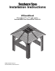
Installation Instructions WillowWood Fits models 7’7” x 7’7” and smaller. Accommodates the Cover Breeze cover lift. © 2001 Sundance Spas, Inc Document Number 6530-188, Rev.
Installation Instructions WillowWood Gazebo How to Use This Manual Thank you for purchasing a Sundance Spas Gazebo. This manual will provide easy to follow, step-by-step instructions for assembly and installation of your gazebo. Please complete the assembly steps in the order they are presented in this manual. Failure to do so will result in an unnecessarily difficult, unsafe or improper installation.
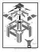
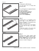
20 12 19 16 13 14 6 7 18 15 17 5 11 4 8 10 1 2 9 3 NOTE: Inner and Outer Sway Braces are to be attached to the inside of the Tie Plates.
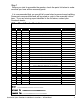
Step 1 Before you start to assemble the gazebo, check the parts list below to make sure that you have all the necessary parts. It is recommended that you pre-drill all screw holes to prevent wood splitting. Some parts are pre-drilled and will be noted as such in the assembly instructions. If you are missing a part identified in the list below, contact your Sundance dealer. WillowWood Gazebo Parts List Item Qty. Part No.
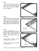
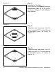
Diagram 2 Step 2 Assemble the Wall Sections You will need a 10' x 10' clear, level assembly area. Lay out the pieces of a single wall section as shown in Diagram 2. A single wall section consists of: one 2"x4"x77-1/2" Header [4], two Lattice Panels [1], and two 2"x3" Uprights [3]. Diagram 3 Step 3 Top edges flush Position the 2" x 3" uprights on the inside edge of each lattice panel as shown in Diagram 3. The notches in the uprights should be face up.
Step 5 Diagram 5 Turn the lattice panels over and position them so that the uprights are facing each other with the notches down, resting on the 2"x 4" header as shown in Diagram 5. Step 6 Diagram 6 Adjust the panel units so the end of the header is flush with the inside edge of the lattice panel frame as shown in Diagram 6. The header should fit snugly in the notches. Secure each lattice panel to the header with two 2-1/2" screws as shown.
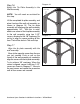
Diagram 8 Step 8 Wall Section WITH corner uprights attached Wall Section WITHOUT corner uprights attached Raise the Wall Sections Have your assistant raise one of the wall sections that has the corner uprights attached. Then raise one of the wall sections without a corner upright. The two wall sections should be positioned as shown in Diagram 8. Close up of wall section with corner upright attached Diagram 9 Step 9 Join Wall Sections on INSIDE of corner upright.
Step 11 Diagram 11 Closing the Wall Sections Place the two completed wall sections opposite of each other as shown in Diagram 11. Join the two wall sections as in Step 9, making sure to attach wall sections to the INSIDE of the corner upright of the adjoining wall. Attach the wall section with four 2-1/2" screws but DO NOT tighten the screws at this time. Pro Tip: You will need an assistant for the next step.
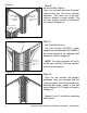
Diagram 13 Step 13 Assemble the Tie Plates Position the four Tie Plates [5] and eight Sway Braces [10 & 11] on the ground as shown in Diagram 13 with all pieces fitting together. Diagram 14 Step 14 Attach the small sway brace to the Tie Plates using two 2-1/2" screws through the pre-drilled holes, as shown in Diagram 14. Diagram 15 Step 15 Attach the large sway brace to the Tie Plates using two 2-1/2" screws through the pre-drilled holes, as shown in Diagram 15.
Step 16 Attach the Tie Plate Assembly to the Wall Assembly Diagram 16 Align this corner first NOTE: You will need an assistant for this step. Lift the completed tie plate assembly, and place it on top of the wall unit assembly, as shown in diagram 16. The tie plate assembly will overhang the wall assembly approximately 1/8". With this in mind, attach one corner of the tie plate assembly to the wall assembly using two 2-1/2" screws, allowing for the 1/8" overhang.
Diagram 18 Step 18 Attach the tie plate assembly to the wall assembly with 2-1/2" screws placed every 10 inches, as shown in Diagram 18. Make sure you check your alignment of the Tie Plate with the wall as you progress. Pro Tip Do not attach mid rafters yet. That comes later. Diagram 19 Step 19 Diagram 19 Moon Lid Cleats Diagram 20 Position the Roof Box Headers, 45 degrees [6] and 90 degrees [7]) on a flat surface as shown in Diagram 19. Moon Lid cleats should be facing the inside of the box.
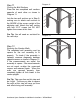
Step 21 Attaching the Hip Rafters Pro Tip: Hip Rafters are 50" long, Mid Rafters are 47" long. To avoid mistakes, lay rafters out side by side and group by length prior to assembly. Position the four 50" Hip Rafters [13] at each corner of the roof box header assembly as shown in Diagram 21. Make sure the hip rafters are positioned with the cleats out and to the ground. See inset of Diagram 21. You are actually assembling the unit upside down. Pro Tip: You will need an assistant for this next step.
Diagram 23 Step 23 Have an assistant hold the hip rafter in position. Place a "Y" Bracket [19] as shown in Diagram 23 and attach with 1-5/8" screws. The "Y" brackets are pre-drilled. Square "Y" bracket to Roof Box first, then align the rafter to the bracket Diagram 24 Step 24 Secure this end LAST Secure this end SECOND Repeat the procedure for attaching the "Y" brackets to the remaining three hip rafters. The completed "Y" brackets should appear as shown in Diagram 24.
Step 26 Diagram 26 Position a Corner Bracket [17] on the tie plate directly under one of the hip rafters as shown in Diagram 26. Attach the bracket only to the hip rafter for now. You’ll attach the tie plate section later. It is best to work from the inside of the gazebo. The entire corner bracket is predrilled with 27 holes. Attach corner bracket only to the hip rafter at this time Step 27 Center each hip rafter on the corner seam of the tie plate as shown in Diagram 27.
Diagram 29 Step 29 Measure and mark the roof box header for the eight panels as shown in Diagram 29. The center point for marking all four headers is 25". Pro Tip: make any marks on the top of the roof box header so they will not mar the finish on the completed gazebo. Pro Tip: To fit the rafter notch squarely on top of the wall assembly, the rafter may be adjusted with up to 1/4" misalignment between the bottom of the rafter and the bottom of the roof box header.
Step 31 Diagram 31 Attaching the Roof Panels The rafter cleats are pre-attached to the roof rafters as shown in Diagram 31. Place a Roof Panel [16] onto the rafter cleats as shown in Diagram 31. Slide the panel forward until it just touches the roof box header. Using too much pressure will cause the roof panel to buckle and rise up. Place one screw in the upper corner of the roof panel to secure it temporarily on the hip rafter side (long rafter). Do not fully attach roof panels at this time.
Diagram 32 Step 32 Once the roof panel is aligned properly, attach it to the hip rafter with one 1-5/8" screw at the top and one at the bottom of the panel. Next, align the mid rafter and also attach it with one 1-5/8" screw at the top and one at the bottom. Do not fully secure the roof panels at this time. Align and attach the next roof panel. Continue until all roof panels are attached to the roof assembly as shown in Diagram 32.
Step 35 Diagram 35 Moon Lid Placement The Moon Lid [19] has two options for installation: Option 1. Sliding Moon Lid Place one Moon Lid Panel inside the roof header box. The single Moon Lid Panel will slide back and forth in the roof header box. This will provide a moon lid that is partially open at all times as shown in Diagram 35. Option 2. Enclosed Moon Lid Place both Moon Lid Panels in the roof Diagram 36 header box for a completely enclosed roof.
Step 37 Maintenance Consult your dealer for any special instructions based on local weather conditions, such as extreme UV (sun) exposure, extreme moisture, etc. In general, wooden surfaces should be cleaned, lightly sanded and restained every six months. Metal roofs should be cleaned with water and a soft cloth only.
Sundance Spas, Inc. 14525 Monte Vista Ave, Chino, CA 91710/U.S.A.; Phone: (909) 606-7733, Fax: (909) 606-0195, Website: http://www.sundancespas.com 6530-188, Rev. B © 2001 Sundance Spas, Inc. Printed in U.S.A.