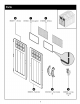
STYLISTIC” Easy Bolt Easy Driver 010210410 % INCLUDED IN KiT www.suncast.com fi 1-800-846-2345 or 1-630-879-2050. BMS6800DW Blow Molded Resin Storage Shed OWNER'S MANUAL Before You Begin « Consult your local authorities for any permits required to construct shed. Prior to the construction of your shed, check with the local building code official to review any required permits or building imitations. + A level and sturdy foundation is required before shed construction can begin.
e « Proper site preparation required. « Shed not intended for use in extreme weather conditions. + Shed not intended for storage of flammable or caustic chemicals. « Store heavy items near the bottom of shed. + Shed not intended for use by children. « DO NOT stand, sit, or store items on storage shed roof. « Treat carefully in extreme temperatures. « Repair or replace broken parts immediately. + Sun cast is not responsible for damage caused by weather or misuse.
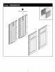
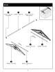
0 0B00075 — Left mid roof 0 x2 0B00076 Right mid roof @ 0631182 Front & back 010208810~ 0630820 — roof support bracket Roof connector Truss bracket x4 x12 X2 ® 0630823 — Truss strap 0630817A * Truss fie down \ ® x4 0631181 [m Mid / roof support bracket 0630819 " Truss cross brace 0630818 — Truss leg x2 x4
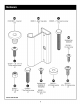
Hardware @ 01020188C1 — Easy Holt x35 0210171 25-20% .75 Phillips machine screw X6 0220047 Nut x24 Shown Actual Size 06308 0200033 1" Hex head cap screw Metal hinge plate X6 0200025 — 2" Hex head cap screw x12 Hardware bag #0480289 0210180 Pan head screw %35 — is Hardware bags 0631023~ 0631022 — #0480290 & #10 Rubber washer ~ #10x .
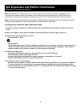
Site Preparation and Platform Construction {Materials NOT supplied with Shed Kit) Note: Site preparation is required for this shed. Placing the shed on a constructed foundation is required. Without a constructed foundation, setting will probably occur, causing distortion and damage to the shed, Sun cast is not responsible for replacing parts damaged or property last due to incorrect assembly. Warranty requires foundation.
Site Preparation and Platform Construction (continue) {Materials NOT supplied with Shed Kit) Anchoring floor panel to concrete slab * Secure shed to concrete pad using masonry fasteners. « Dimensions allow for shed to fit within the nearest 1" on each side. Outside to sealer of (B) hoard Wood platform critical spacing " * Check all critical spacing measurements. 138° 1814 Suk frame spacing 1138 0474 Anchoring floor panel to wood platform * Secure shed to wood platform using 1/4" x 3" lag screws.
Door Pr-Assembly Peel film from both sides of window {S). Lay deft door (N} on flat ground with the window screw attachments facing up. Layer into the door channel first the window gasket (T}, then the window (S). Cut excess gasket length. Through the back of the door, secure layers with thirteen screws {(NN) {start with four corner screws and then finish with remaining screws). DO NOT over tighten screws.
At the bottom interior side of left door, attach D-ring slide bolt {V) with four screws (MM) through provided holes. Header Pr-Assembly Slide roof ridge beam bracket (W) under tabs on the inside peak of the front header (K} and secure with two screws (MM). DO NOT over tighten screws. Repeat for rear header {L).
Lay front header (K} on ground with lettering facing up. Place vent screen {Z) into rear opening in front header (K}. Secure through back of header with eight screws (NN). DO NOT over tighten screws. Repeat for rear header {L}. Truss Pr-Assembly Place one truss leg {CC) at each side of the truss bracket (BB). Place truss cross brace (DD} under both truss legs.
Attach truss legs to truss bracket using one 1" hex head cap screw (LL) and one nut (KK) at each end of bracket. Attach truss cross brace to truss legs using one 2" hex head cap screw (Il) and one nut (KK} at each end of truss cross brace. Stand A-configuration truss on its feet and check truss cross brace is level. Repeat Steps 6 and 7 for second truss. Place one truss tie down (FF) at each end of truss legs {CC). Secure each truss tie down with one 2" hex head cap screw (I} and one nut (KK).
KK). 1} and one nut ( Insert the roof ridge beam extension (Y} into the ridge beam (X). Secure with one 2" hex head cap { screw Shed Assembly Align the tongue in front floor (A} with the groove in mid floor (B} and secure with four screws (NN}.
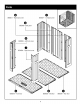
Align the tongue in mid floor (B} with the groove in rear floor (C) and secure with four screws (NN). Critical: Flex left front corner (D) hinge back and forth several times. This will help provide a square corner and ensure proper fit of remaining panels. ~ l With at least two people, align the tab on the bottom right side of the left front corner (D) with the slot on front floor (A). Lower the panel into the slot and lock in place by sliding the panel toward the door opening.
Tip the left front corner (D) outward slightly. Bend the corner, then tip the panel back to vertical position, making sure to align the lower tabs on the right side with the slots in the front floor. Before proceeding, make sure the corner is square where it meets the floor and that the panel is flush with the floor. If not, repeat Steps 12 and 13 until square and flush.
Secure the corner with four easy bolts Work from floor to roof. DO NOT use torque wrench. Use easy bolt easy driver and hand tighten. Easy bolt head will be flush when fully seated. DO NOT over tighten easy bolts. Note: You may hear a click when the easy bolt has been tightened completely. Repeat Steps 14 and 15 for next left side panel. Critical: Flex left back corner (F) hinge back and forth several times. This will help provide a square corner and ensure proper fit of remaining panels.
Tip the left back corner (F) outward slightly. Bend the corner hinge, then tip the panel back to vertical position making sure to align the lower tabs on the left side with the slots in the rear floor. Left back corner should align and overlap previously installed side panel. Before proceeding, make sure the corner is square where it meets the floor and that the panel is flush with the floor. If not, repeat Steps 16 and 17 until square and flush.
With at least two people, align the tabs on the bottom of back panel (G) with the slots along the rear floor. Lower back panel into the slots and lock in place by sliding the panel forward the corner. Note: To allow the back panel to overlap left back corner, tilt out slightly as you slide it into position. Note: Use a rubber mallet to “push” side panel (G) into socked position, aligned with left back corner. Secure the back panel with four easy bolts (GG). Work from floor to roof. DO NOT use tongue wrench.
Critical: Flex right back corner (Hj hinge back and forth several times. This will help provide a square corner and ensure proper fit of remaining panels. I | With at least two people, align the tabs on the bottom left side of right back corner {H) with slots along rear floor. Lower the panel into the slots and lock in place by sliding the panel toward the back panel. Note: To allow the right back corner to overlap back panel, it out slightly as you slide it into position.
Secure the corner with four easy bolts (GG). Work from floor to roof. DO NOT use torque wrench. Use easy bolt easy driver and hand tighten. Easy bolt head will be flush when fully seated. DO NOT over tighten easy bolts. Note: You may hear a click when the easy bolt has been tightened completely. With at least two people, align the tabs on the bottom of side panel (E) with the slots along the mid and rear floor.
Secure to the corner with four easy bolts {GG). Work from floor to roof. DO NOT use torque wrench. Use easy Holt easy driver and hand tighten. Easy bolt head will be flush when fully seated. DO NOT over tighten easy bolts. Note: You may hear a click when the easy bolt has been tightened completely. Repeat Steps 24 and 25 for next right side panel. Critical: Flex right front corner (J} hinge back and forth several times. This wail help provide a square corner and ensure proper fit of remaining panels.
Tip the right front corner {J) outward slightly. Bend the corner hinge, then tip the panel back to vertical position making sure to align the lower tabs on right side with the slots in the front floor. Before proceeding, make sure the corner is square where it meets the floor and that the panel is flush with the floor. If not, repeat Steps 26 and 27 until square and flush, — Top view Side view Secure the corner with four easy bolts (GG). Work trim floor to roof. DO NOT use torque wrench.
With at least two people, place front header (K) over the door opening and fit the two protruding support legs on the left and right front corners into the pockets molded in the front header. Tabs on front header must be seated in header channel pocket. Note: DO NOT leave front header unsupported unit header beam (AA) is secured {step 30). Secure the front header with the header beam (AA) and attach with six screws (NN). Note: Header beam (AA) has large holes on one side and small holes on the other side.
Stand the right door (M) upright with the three hinge mounts facing right. Slide one metal hinge plate {HH) onto each hinge mount. Rotate the hinge plates to the outside of the door. Snap the metal hinge plate into place by pushing towards door. Repeat for left door (N} Rotate metal hinge plates to open position. x3 Slide one metal hinge plate over each hinge receptacle on the inside of right front panel. Secure each metal hinge plate with one screw (JJ} and one nut {KK}. Repeat for left door (N).
With at least two people, place rear header (L} over the back walls and fit the two protruding support legs on the left and right back corners into the pockets molded in the rear header. Tabs on rear header must be seated in header channel pocket. Note: DO NOT leave rear header unsupported unit header beam (AA) is secured (step 34). Secure the rear header with the header beam (AA) and attach with six screws (NN).
With at least two people, slide the truss assemblies into place, then secure 1o the side panels with four screws {NN} in each truss tie down. Note: This may require the side panels to be pushed inwards or outwards slightly as the brackets are slid into place. With at least two people, raise the ridge beam assembly up and into the rear roof ridge beam bracket. Secure with one 2" hex head cap screw (I} and one nut (KK).
With at least two people, slide the ridge beam assembly into the front roof ridge beam bracket. Secure with one 2" hex head cap screw (I} and one nut (KK). Note: Alignment of the ridge beam to the bracket may require the header panels to be pushed inwards or outwards slightly as the ridge beam is slid into place. Locate and identify channels on interior side of one right roof {O). Locate three underside tabs contained within the channels.
With at least two people, lay right roof (O} directly over the three tabs on the right side of the front header. With the right roof channel seated overfond the header tabs, pull the right roof downward at each header tab until the roof snaps in place. With a second person, pull down each lower corner of roof from outside. From inside shed, attach tabs 40 on side panel (E} and front right corner {J} to the root panel with a screw (NNJ.
Press edge of right roof (O) into channel on fuss leg (CC). With at least two people, lower the right mid roof (P) onto the roof trusses.
With a second person, pull down each lower comer 4 of roof from outside. From inside shed, attach tabs side panels (E) to the roof panel with a screw (NN}, j] Press edge of right mid roof (P) into channel on truss leg (CC). ‘¥ End view .
Secure right roof panels to truss with three roof connectors (EE} in corresponding slots in roof panels. N\ To lock in place, the top and middle connectors slide up and the bottom connector slides down, per illustration shown below. Top Middle Bottom O O @ For clarity, illustration is Shawn with left front corner Note: Have a second person push roof panels and left door removed. together to more easily lock roof connectors on. Locate and identify channels on interior side of remaining right roof (0).
With at least two people, lay remaining right roof (O) directly over the three tabs on the right side of the rear header. With the right roof channel seated over/ on the header tabs, pull the roof downward at each header tab until the roof snaps in place. With a second person, pull down each lower corner of roof from outside. From inside shed, attach tabs on right back corner (H} and side panel {E} 1o the right roof with a screw (NNJ.
Secure right roof panels fo truss with three roof connectors (EE) in corresponding slots in roof panels. N To lock in place, the top and middle connectors slide up and the bottom connector slides down, per illustration shown below. Top Middle Bottom O OO For clarity, illustration is Shawn with left front corner Note: Have a second person push roof panes and left door removed. together to more easily lock roof connectors on. Locate and identify channels on interior side of one left roof (Q).
With at least two people, lay left roof (Q) directly over the three tabs on the right side of the front header. With the left roof channel seated over/on the header tabs, pull the roof downward at each | header tab until the roof snaps in place. | With a second person, pull down each lower corner of root from outside. From inside shed, attach tabs on left front corner (D} and side panel (E) to the deft roof with a screw {NNJ.
Press edge of left roof (Q) into channel on truss feg (CC). End view With at least two people, lower the left mid roof (R} onto the roof trusses.
With a second person, pull down each lower comer of roof from outside. From inside shed, attach tabs on side panels (E) to the left mid roof with a screw (NN). Press edge of left mid roof (R) into channel on truss leg (CC).
Secure left roof panels o truss with three roof connectors (EE) in corresponding slots in roof panels. £ rd To lock in place, the top and middle connectors slide up and the bottom connector slides down, per illustration shown below. Bottom Middle Top For clarity, illustration is Shawn with left front corner Note: Have a second person push roof panels and left door removed. together to more easily lock roof connectors on. Locate and identify channels on interior side of left roof (Q).
With at least two people, lay remaining left roof (Q} directly over the three tabs on the left side of the rear header. With the left roof channel seated over/ on the header tabs, pull the roof downward at each header tab until the roof snaps in place. With a second person, pull down each corner of roof from outside. From inside shed, attach tabs on the left rear comber (F) and side panel {E) to the left roof with a screw (NN}.
Secure left roof panels o truss with three roof connectors (EE) in corresponding slots in roof panels. £ rd To lock in place, the top and middle connectors slide up and the bottom connector slides down, per illustration shown below. Bottom Middle Top 5o Note: Have a second person push roof panels together to more easily sock roof connectors on. For middle and upper roof connectors, install one screw (MM) into truss behind roof connectors, Repeat for remaining four roof connectors.
Attach door handle (U} to left door with two screws {NN). Repeat for right door. Attach one truss strap (OO} at each end of truss legs. Secure each truss strap with two screws (MM}, Repeat for second truss.
Secure roof panels together along the ridge of roof using six rubber washers {PP) and six sealing screws (QQ). For clarity, illustration is shown with right side panels and front header removed. Raise mid roof support bracket (RR] into position against roof, Secure mid roof support bracket (RR) to underside of roof using two screws (NN). Note: Mid roof support brackets (RR) are longer in length than the front and back roof support brackets (SS).
Raise front roof support bracket {88} into position against roof. Slide front roof support bracket (88) into front header {K). Secure front roof support bracket (88) to underside of roof using two screws (NN). Repeat steps 66-68 for remaining roof support brackets.
SUNCAST® Building, Shed and Gazebo Ten Year Limited Warranty Your SUNCAST® Building, Shed or Gazebo has & TEN YEAR LIMITED WARRANTY against product failure resulting from defects in manufacturing or materials. The warranty period starts on the delivery date. Incidental and consequential damages are not covered. Warranty Claims To file a warranty claim contact the manufacturer, SUN CAST ® CORPORATION, 701 North Kirk Road, Atavist, Illinois, 60510, Call toll free (800} 846-2345 or visit www. Suncast.