
Operating Guide


3
INSTALLATION
Layout and Drilling
1. Determine general location of the TV.
2. Use a stud nder to nd the nearest wall studs if applicable and mark their location.
3. Tape template at and level to wall surface, aligning the template’s slots with the stud markings on the wall.
NOTE: Use of a bead level is recommended.
NOTE: Template corners fold up to catch debris.
4. Use a pen or pointed object to mark bore locations.
ATTENTION: Before drilling, verify there is a minimum of 1-3/8" of concrete thickness to be used for the
concrete anchors. Ensure to mount in a solid part of the block, generally 1" minimum from
the side of the block. Cinder block must meet ASTM C-90 specifications.
ATTENTION: Concrete must be 2000 psi density minimum. Lighter density concrete may not hold concrete
anchor.
ATTENTION: A standard electric drill on slow setting should be used to drill the holes instead of a hammer
drill to avoid breaking out the back of the hole when entering a void or cavity.
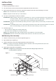
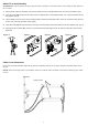
5. Drill holes (Figure 1):
• Use 1/4" bit for drilling into wooden studs (x4).
• Use 5/16" bit for drilling into concrete wall (x6).
NOTE: Two additional holes and provided anchors are needed for concrete installs.
ATTENTION: Be sure to drill holes centered within studs. Do not drill into mortar joints.
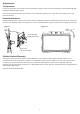
Wall Mounting of Arm Assembly
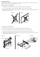
1. Hammer concrete anchors (Y) into wall as applicable (Figure 1).
2. Apply washers (Z) to lag bolts (X).
3. Hold Arm Assembly in place while applying lag bolts (X) with washers (Z).
NOTE: A properly mounted Arm Assembly will be oriented so that its Keyed Notches side of the
Arm Assembly Head Mount is upward.
4. Tighten bolts snugly without overtightening.
CAUTION: Overtightening can damage the bolts and reduce their holding strength. Refer to the
mounting template for specics.
Figure 1
5/16" Holes for Concrete
1/4" Holes for Studs
Arm Assembly
Keyed
Notches
Head Mount
Concrete Anchors
(for concrete only)
Washers
Lag Bolts (X)